General presentation
Introduction
The FloorTools User Manual is written to provide guidance on how to perform a structural substantiation of seats and monuments installation on floor structure. A fully automated process has been encapsulated in the FloorTools software to enable a fast and efficient validation of various cabin seating configurations.
Throughout this User Manual seating installations are classified in “Standard” (std) seat installation or “Non-Standard” (non-std) seat installation.
Standard seat installation
Standard seat installation refers to seating configuration covered by airplane OEM manuals. For instance, on a wide body aircraft, a 10 abreast (3-4-3) economy class seats installed with valid pitch can be classified as standard seat installation.

Fig. 1 Photo of typical standard seating installation (3-4-3 Economy Class)
Standard seating installation is justified based on OEM requirements. Several criterion have to be fulfil to ensure a safe standard seat installation (seat interface load below OEM allowable, seat mass below floor structure running load allowable, etc…) .
Non-Standard seat installation
Non-Standard seat installation refers to seating configuration not covered by OEM specifications. Non-Standard seat installation is used generically to refer to seats and / or monuments installed on floor structure. Typically a non standard seating installation could be a business class configuration with seats and surrounding shells. In such an installation seats are often staggered (no straight row) and multiple interface loading from seats and surrounding monuments prevent the direct use of OEM requirements for passenger seat installation.

Fig. 2 Photo of typical non standard seating installation (AF Business Class)
The validation of non standard seating installation is mainly based on a comparative analysis with standard seating configuration. In the FloorTools several “critical” standard passenger seating configurations have been captured and used as Reference Loading. Those installations have been optimised to maximise the interface load applied on the floor structure whilst passing all the OEM requirements.
Warning
In the current FTools version Non-Standard seat installation is restricted to Boeing B777-300 between STA382 (X=382in) and STA2033.50 (X=2432.5in). Only standard seat installation can be performed on Boeing B777-200.
Note
Throughout this document the FloorTools software will be referred as FTools.
FTools process overview
Before starting an analysis, a review of the FTools general process could help to understand its mechanism. The FTools analysis is based on a three step process:
Validation of Loading Input Data and its binding to a floor structure configuration (fsconf)
Definition of LOPA zone(s) to analyse and for Non-Standard seat installation only, selection of loading reference(s) to use for comparative analysis
Launching the installation analysis
Once the Loading Input Data is validated the analysis can be launched and the FTools will run through its internal process shown in Fig. 3
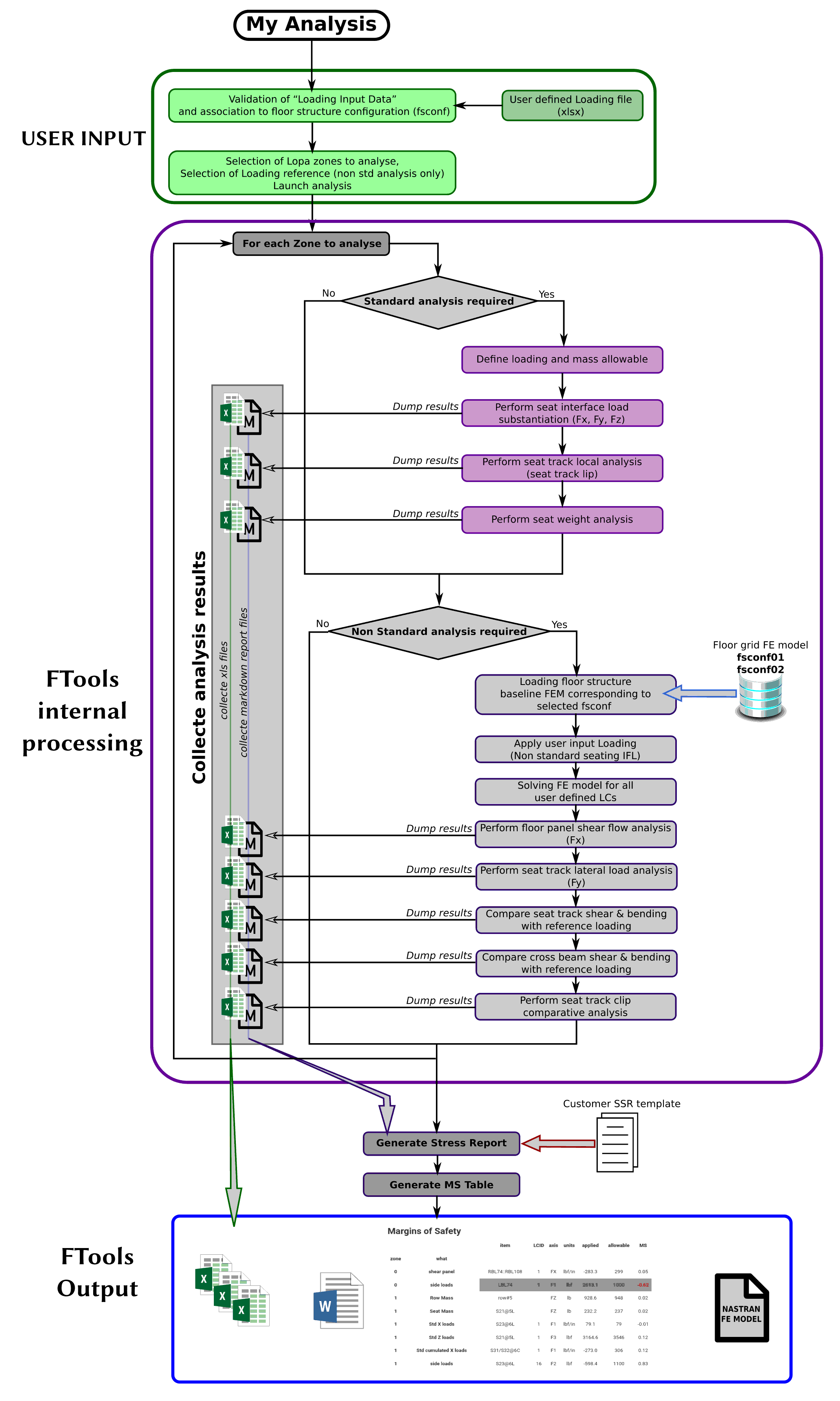
Fig. 3 FTools process overview chart
At the end of the internal process a result page appears with a Margin of Safety table summarising the most critical results and a list of downloadable output files. This list of available output files depends on the type of analysis performed (Standard / Non-Standard). Refer to Understanding output files for more information on FTools output files.
Note
The granularity of the analysis type is a LOPA Zone. The type of analysis performed on a LOPA Zone is related to a user input analysis field in the Loading Input Data.
Warning
The specification of one cabin item as non-std in a LOPA Zone triggers a Non-Standard analysis for the complete Zone.
Filling an XLSX spreadsheet
The input files of the FloorTools are in the format of XLSX spreadsheet. It offers a great flexibility and ease of inputting data although it requires some rules to follow. The FloorTools software is built to automatically read the XLS file provided. At a first stage a “validator” module will check that the expected data are found in the XLS file and that they have been input in the required format.
This validator can also be used directly to check on input file independently (link to FTools validator)
Some general rules about the XLS file filling
column with header can’t be deleted
default column header can’t be renamed
data can’t be entered in column with no header
calculation or comment can be added in a new column with a new header (the FloorTools reader will ignore it)
Line 1 and line 2 shouldn’t be deleted
template sheets shouldn’t be renamed
new sheet can be added (the FloorTools reader will ignore it)
In each spreadsheet the first line is the line defining the field label. The second line is used to specify the data unit when relevant. In each cell of the column header a comment can be displayed to get information regarding the data type expected by the software.
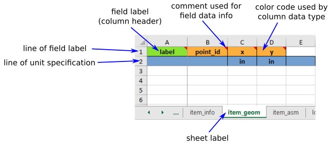
Fig. 4 Input spreadsheet general information
Note
When necessary, unit specified in line two of a data field can be modified to another consistent unit. For instance “in” can be modified to “mm” or “ft”.
Column header color code
Three different colors can be found in the cell of the column header:
orange for mandatory field
white for optional field
green for padded field
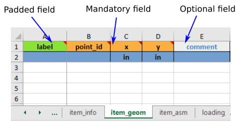
Fig. 5 Input spreadsheet header color
Note
Padded field means that the data doesn’t have to be repeated on each line. The software reader automatically assumes that the entered data is repeated on the blank line below until a new entry is found.
Here below is an example of padded entry:
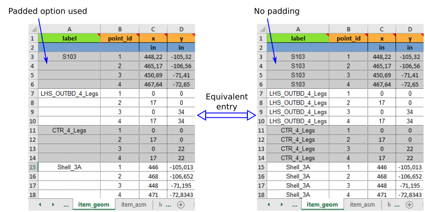
Fig. 6 Example of padded entry
Warning
If padded entry is used the first entry of the block can’t be blank. For instance, on the example above, label in line 3 of the first padded entry can’t be blank.
Field data type
- In each column header a comment is added to indicate the data type of the entry expected. For instance, in the example of Fig. 7, data entered in column B, “point_id” should be
an integer number. This field data type information is also available in each field description information text.
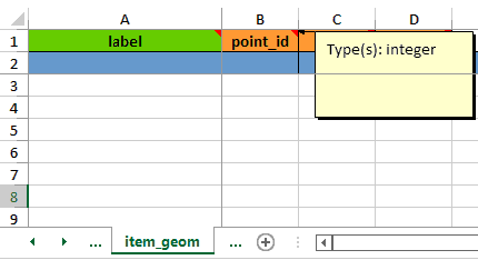
Fig. 7 Example of field data type
Understanding sheets cross references
When filling the xlsx template one need to understand that some fields are linked between different sheets. Cross link fields are labelled with the combination of the “Sheet label” and “column label” separated by “::”

For instance on Fig. 8, in sheet “item_asm” two cross reference fields are specified. In column C, “item_geom::point_id” refers to a ‘point_id’ of the sheet “item_geom”. In column D, “item_info::label” is used to refer to a ‘label’ of the sheet “item_info”.
When a cross link field is specified, the data entered in the source sheet should perfectly match the label in the target sheet (it is case sensitive and there should not be any trailing space difference). For instance in “item_asm” sheet, ‘S59’ in cell D2 is exactly the label entered in sheet “item_info” cell B3.
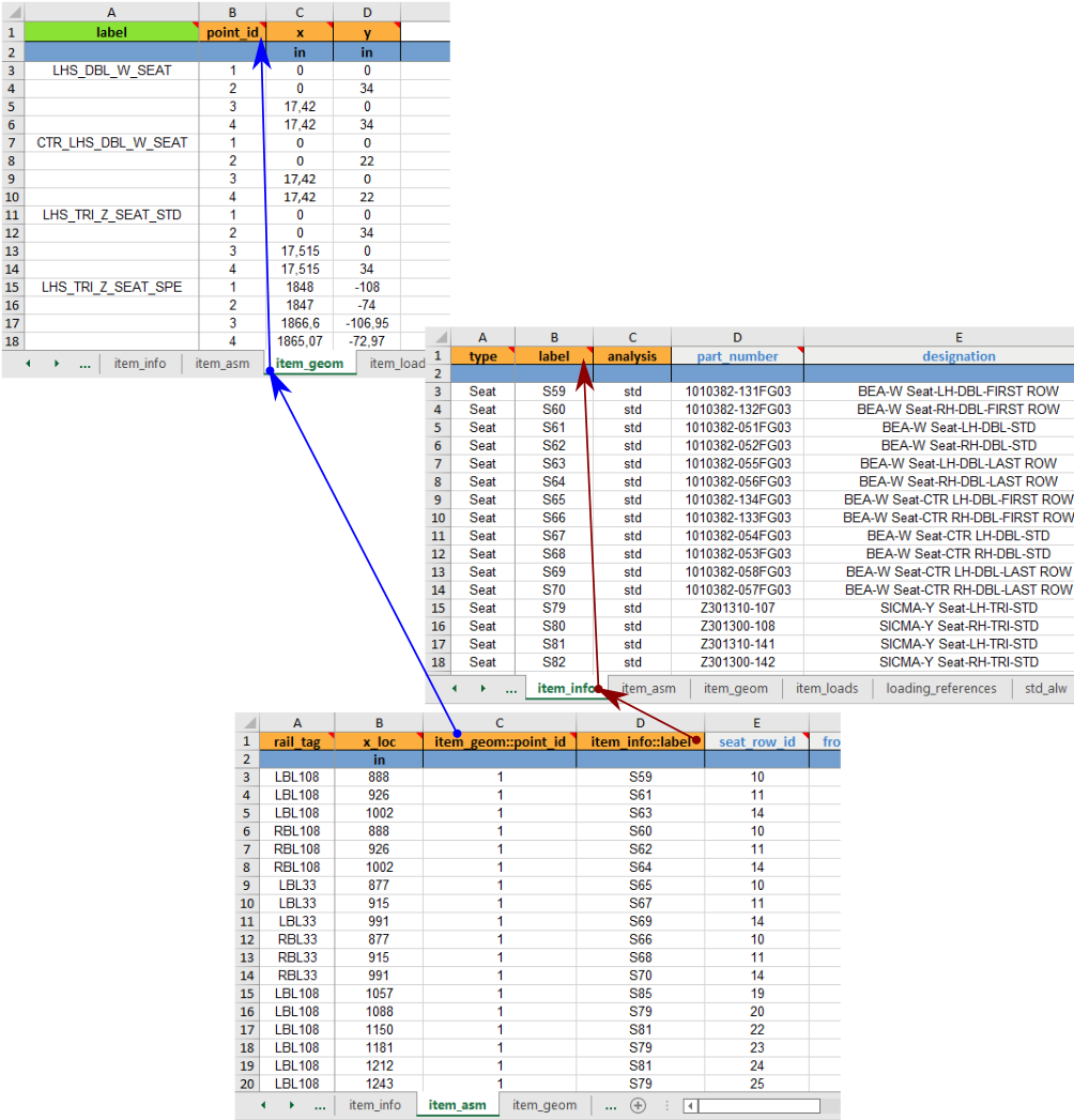
Fig. 8 View of item_asm sheet cross references
A general overview of relationships between tabs is shown Figure Fig. 33.