Tutorial 01 - Capturing a LOPA
Fill in a loading input file to create a LOPA on FTools
Tutorial objectives
Part 1: capturing Non Standard seats (Part 1. Fill in the input file with Non Standard seats)
Part 2: capturing Standard seats (Part 2. Fill in the input file with Standard seats)
At the end of this tutorial, FTools user should have reviewed necessary knowledge to prepare a Loading Input Data spreadsheet for a complete LOPA.
Introduction
The Loading Input Data spreadsheet is the main source of input data for the FTools to perform an automatic seat installation analysis. There are two files: one in metric units and one in imperial units. The user should download the required file. In this tutorial, we will base our demonstration on the Imperial units sheet as we will be working on a Boeing aircraft. The purpose of this tutorial is to guide new users through the process of filling in this spreadsheet. The aim of this tutorial is to complete the FTools spreadsheet for a complete B777-300 cabin LOPA as shown in Fig. 83. This tutorial is based on the following cabin configuration: Business Class seats, Premium Economy Class seats and Economy Class seats. Through this tutorial, we’ll look at the notion of zone, which corresponds to the separations made by the FTools software itself. These separations are generated automatically when no items are installed in a large enough space.

Fig. 83 View of a complete B777-300ER cabin LOPA on FTools
There are several sheets in the Loading Input Data spreadsheet, but in this tutorial we will only focus on the following 3, which are:
Sheet “item_info”, which is the definition of the seats and monuments installed in the cabin. This sheet allows you to centralise the main information and characteristics of each item.
Sheet “item_geom”, which is the definition of seats, monuments, and cabin item attachment points geometrical spacing in a defined coordinate system.
Sheet “item_asm” which is the location of seats and monuments on the cabin LOPA
For further information on these sheets and how they are created, please refer to the Loading Input Data section.
Preliminary work (optional)
To ensure the success of your study and the accuracy of your data entries, it may be useful to carry out some preliminary identification work. This work can be done at the user’s discretion, but here is a non-exhaustive list of some useful software programs for clear, visual work:
Inkscape (this powerful software is free, allows you to draw what you want and works with the vector approach, which means that you do not lose any quality in your drawings when you need to zoom in).
Paint
Powerpoint
The main aim of this part is to find out exactly which seat group has the same wheelbase and the same interface loads. This information can be found in the seat documentation supplied by the manufacturer. This will be very useful later in the tutorial, especially for filling in the spreadsheet. In the following figures we can see the preliminary work done for the wheelbase in Fig. 84 and the preliminary work done for the interface loads in Fig. 85.
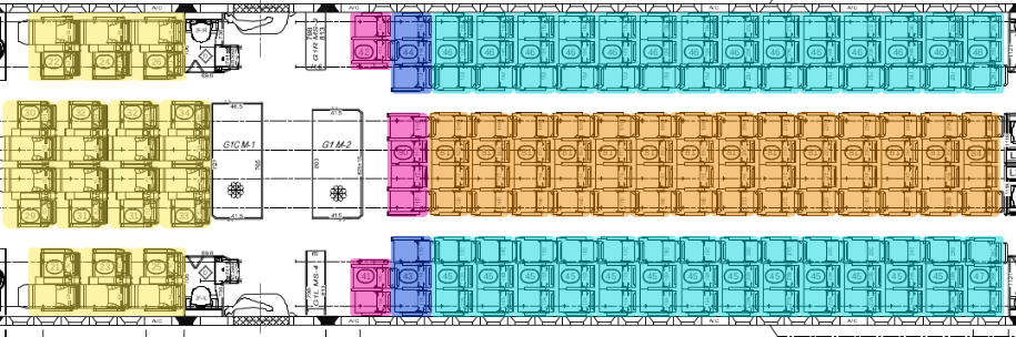
Fig. 84 Visualisation of seat group sharing same wheelbase (example on LOPA Zone 1 & 2)
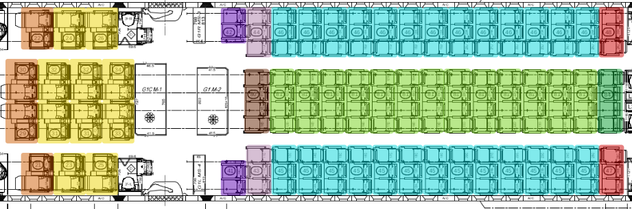
Fig. 85 Visualisation of seat group sharing same interface loads (example on LOPA Zone 1 & 2)
Warning
Several seats may have the same wheelbase but different interface loads. The user must therefore be very careful during this identification work, as there is a risk of making mistakes later when filling in the spreadsheet.
Part 1. Fill in the input file with Non Standard seats
Part 1 objectives: fill in the FTools spreadsheet for any non-standard cabin configuration.
Tutorial running time: TBD
In this section we will focus on the Business Class seating area. Zone 0 consists of 14 business class seats as shown in Fig. 83. The visualisation of the LOPA is available in Fig. 86 with seat numbers used to fill the spreadsheet.
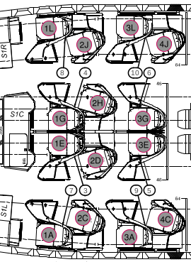
Fig. 86 Focus LOPA on zone 0 with business class seats designation
For better understanding, some seats and shells in zone 0 have been highlighted to illustrate the parallel between filling in the spreadsheet file and LOPA’s visual information. These markings can be seen in the Fig. 87.
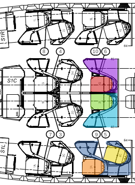
Fig. 87 Identification of some seats to illustrate the parallel with the spreadsheet infos
Before starting the tutorial, it is important to know that in the following parts we will only develop the filling method for a few seats/furniture. The other seats/furniture will have to be filled in by the user. All information is available in the PDF document below.
PDF document: Required_data_for_zone0.pdf
item_info sheet
All the following explanations are illustrated in the Fig. 88 and Fig. 89.
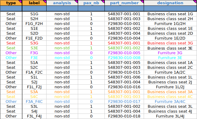
Fig. 88 First 6 columns of the item_info sheet
type column: here we need to specify what type of item we have. You can choose between “Seat” or “Other”. Here, for the Business Class zone, we need to look at the items installed. A business class suite (in our case) consists of a seat and a shell around it. It is very important to clearly identify both in order to enter the correct information in the spreadsheet. As we can see on Fig. 88, we have specified “seat” for the seats and “other” for the surrounding shells.
label column: in this part we give the name that will appear on the final LOPA for this item. Here we have labels starting with “S” for the seats followed by a number and a letter for the Business Class Suite row as mentioned in the initial LOPA. For the surrounding shells, the naming method is exactly the same as for the seats. We can also see that we have different names for the surrounding shells (F3G and F3A_F4C). This is because we have 2 types of business class suite in our configuration. For example, on the Fig. 87, the clear blue shell contains only seat 3E (green), while the dark blue shell contains seat 3A (orange) and 4C (yellow). We will see the differences later when filling the item_geom sheet.
Note
In our case, we choose to start our shell label with “F” for “Furniture” because the “S” for “Shell” is already taken by the seat label. It is important to note that you can use any letter in this column to name your item on the final LOPA, but we always try to write something that will be easy to identify on our final work.
analysis column: in this column we specify the type of analysis required to justify the cabin seat and monument. We have the choice to enter “std” for standard analysis or “non-std” for non-standard analysis. Due to the geometry and layout of the Business Class suites, we will enter “non-std” for our seats and furniture because we can’t use directly the Boeing justification criterion.
pax_nb column: in this column we indicate the number of passengers on each seat. In our case, we have 1 pax on each Business Class seat and no pax on the furniture lines.
part_number column: here you need to enter the item number. This reference can be found in the seat/furniture manufacturer’s document.
designation column: here you must enter a text to describe the item. This is a free format text, so you can enter any text you like. In general, we use the same name as in the original LOPA or in the seat manufacturer’s documents to make identification easier.
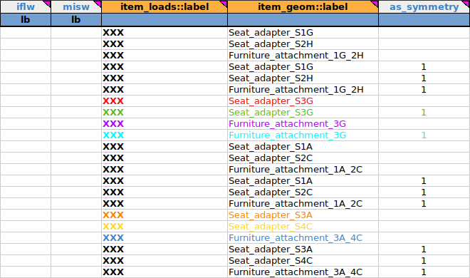
Fig. 89 Last 5 columns of the item_info sheet
iflw column: we don’t need this column for this tutorial. As the identification code is white (optional), we will leave this part blank.
misw column: same as iflw
item_loads::label column: it defines the label to be linked to the interface loads (IFL) associated with the cabin seat or monument. This is a cross reference to the item_loads sheet. We don’t need this column for our tutorial, but as it is a mandatory field, we will just enter “XXX” once in the “label” column in the item_loads sheet and for all lines in the item_info sheet. The way to do this is shown in Fig. 90.
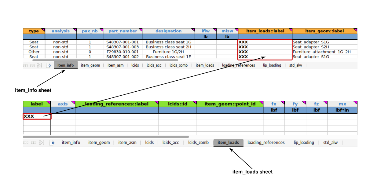
Fig. 90 Avoiding errors with the “XXX” tip
item_geom::label column: it defines the label to be associated with the location of the interface points associated with the cabin seat or monument. This is a cross reference to the sheet “item_geom” which is filled in after the sheet “item_info”. Again, you can choose any name you like, but it is still better to choose one that is easy for the user to associate with references on the original LOPA.
Note
As we can see in Fig. 89, some items have the same item_geom::label:. This can be explained by the fact that some items are symmetrical inside the cabin. This information can be found in the seat manufacturer’s documentation. At this point it is useless to create 2 labels in the item_geom sheet, we will select one and symmetrize the other (this operation will be explained later in the as_symmetry column). For example, this is the case for “Seat_adapter_S3A”, “Seat_adapter_S4C” and “Furniture_attachment_3A_4C”. Seats 3L and 4J are the right cabin items symmetrical to seats 3A and 4C left cabin items. The visual representation is shown in Fig. 86.
as_symmetry column : it indicates whether the associated interface load and geometry should be made symmetrical for the seat or monument. If this is the case, the user should enter ‘1’ in this field. As we have seen, seats 3A and 4C are symmetric with 3L and 4J, so we enter “1” in this column to identify these seats as symmetric with each other (for these elements, FTools will reverse the Y values but leave the X values unchanged). The visual representation of the spreadsheet for this type of configuration can be found in Fig. 91.
Warning
This option can only be applied to seats or monuments that have the same interface load source and the same interface point geometry. This option will symmetrize both the load and the geometry. As we are focusing on geometry only in this tutorial, we will only look for geometry data in the seat manufacturer’s documents.
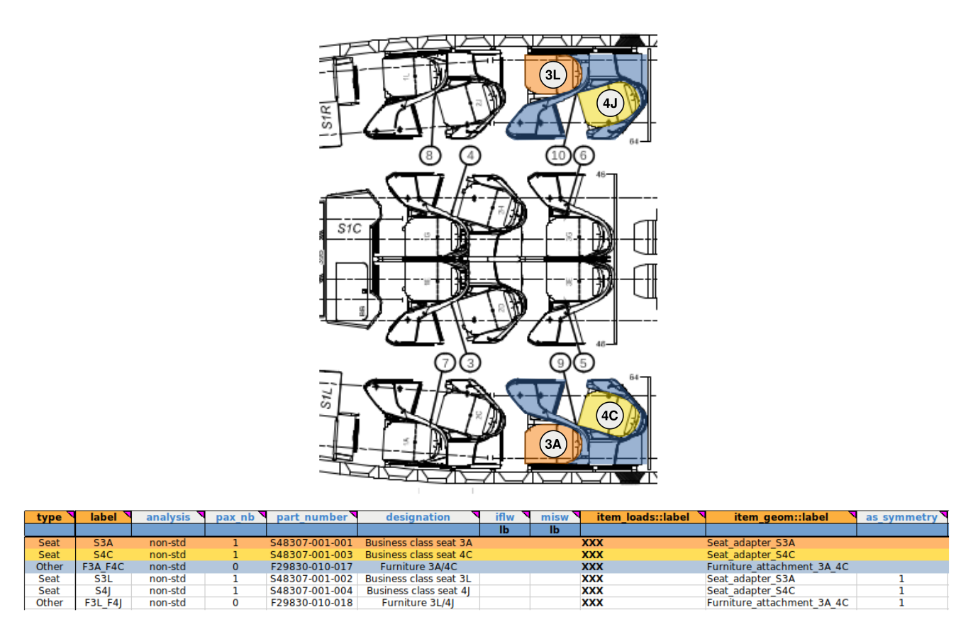
Fig. 91 Symmetric visualization for seats and furniture
item_geom sheet
The purpose of this sheet is to define the position of the interface points of an element relative to each other. It is important to note that interface points can be entered in 2 different ways:
Absolute coordinates: interface points are entered directly into the aircraft’s coordinate system as described in Fig. 92
Relative coordinates: interface points are entered into a local coordinate system associated with the element
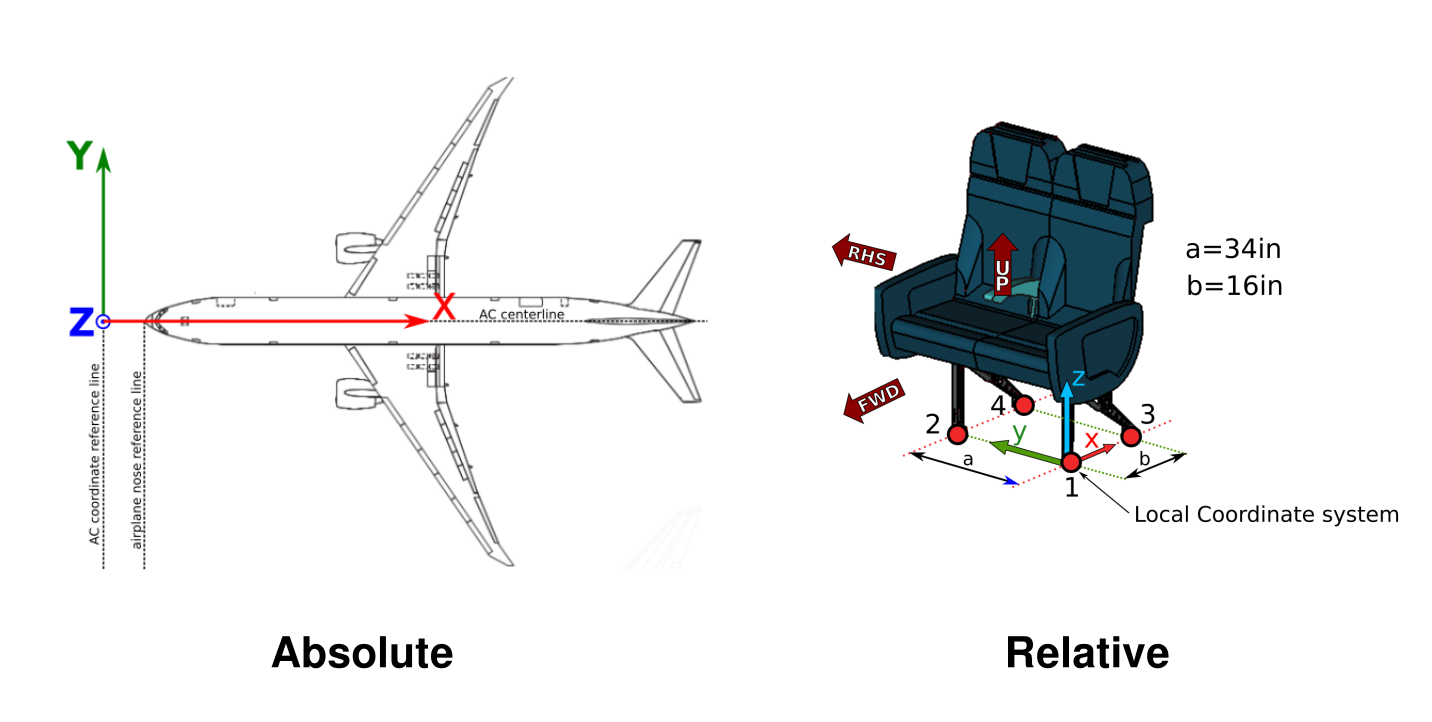
Fig. 92 Absolute vs relative coordinates system
To recapitulate, the location of the interface points can be entered in the local or global coordinate system, as long as it remains consistent from element to element. In both configurations, the axes of the FTools coordinate system are oriented in the same direction as the Boeing standards:
X pointing aft
Y pointing starboard (Right Hand Side)
Z pointing up
Warning
The interface point on the X-axis in absolute coordinates should not be confused with aircraft stations (STA). The Boeing 777-300 has 2 additional sections compared to the Boeing 777-200. See below for details.
From STA 825 the user must add +21” for each of the next 10 frames (up to +210” for the tenth). For example, if your interface point is at STA 846 on a B777-300, it should be converted to X= 846” + 210”.
From STA 1434 the user must add +21” for each of the next 9 frames (up to +189” for the ninth). For example, if your interface point is at STA 1476 on a B777-300, it should be converted to X= 1476” + 210” + 189” (because we have already added the first section from STA 825).
The visualisation of these 2 added sections is available in Fig. 93. This information is not important for now, but will be useful for part 2 of tutorial 01 Part 2. Fill in the input file with Standard seats as we will work in the aft fuselage zone.
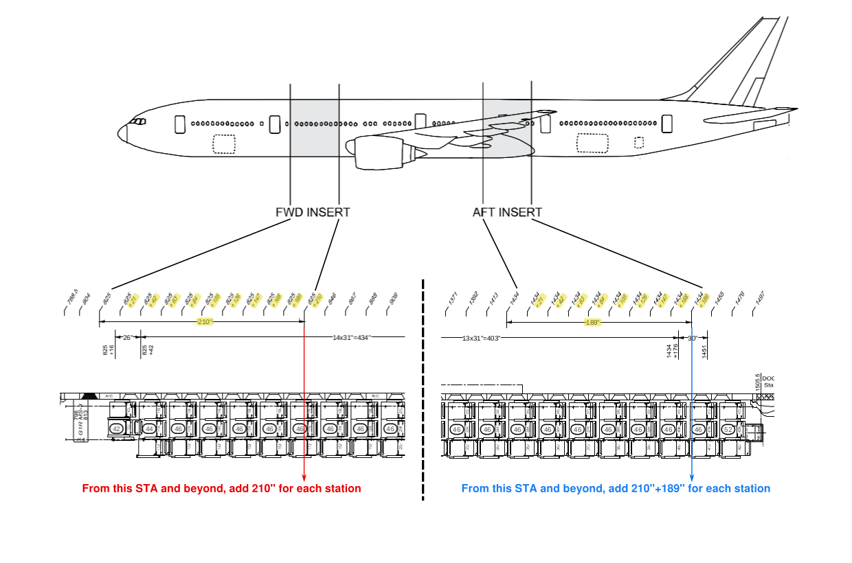
Fig. 93 Added stations zones
The item_geom sheet is composed by 4 columns presented in Fig. 94.
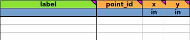
Fig. 94 item_geom sheet empty
label column: this is a label associated with the geometry of the item defined in the item_info sheet. The label must be entered as text without spaces, use underscores instead.
Note
As we have seen, some items in the business class zone are symmetrical to each other. We will just fill in the information for one and use the as_symmetry column in the item_info sheet for the other.
For maximum clarity, here is the cabin layout for our tutorial:
Type |
Label |
Symmetric to |
|---|---|---|
seat |
1L |
1A |
seat |
2J |
2C |
seat |
3L |
3A |
seat |
4J |
4C |
seat |
1E |
1G |
seat |
2D |
2H |
seat |
3E |
3G |
furniture |
1L/2J |
1A/2C |
furniture |
3L/4J |
3A/4C |
furniture |
1E2D |
1G/2H |
furniture |
3E |
3G |
point_id column: this is where we specify the item’s interface points. It is possible to number the interfaces as you wish, but it is often more convenient to use the IDs given in the supplier’s document. This action will be important for tutorial 02 on interface loads.
Warning
The “point_id” must be unique per item !
X column: enter X location of cabin item interface point in relative or absolute coordinates.
Y column: enter Y location of cabin item interface point in relative or absolute coordinates.
In this tutorial we will focus on seats 4C and 1G for the classic fuselage section and seat 1A for the canted fuselage section.
classic fuselage section
The classic fuselage section is where the rails on the aircraft floor run straight along the cabin. In our example, business class seats are non-standard seats as they are not directly attached to the aircraft rails but are connected to an adapter. For these seats, the data to fill in the spreadsheet is the adapter data on the manufacturer’s documentation. As a reminder to understand the next part, on the Boeing 777-200 and 777-300 there are 4 rails on each side of the cabin. These rails are described in detail in Fig. 95.
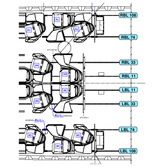
Fig. 95 Rails identification on Boeing 777-200/-300
Seats
Let’s start with the S4C adapter. As we can see in Fig. 96, we have the X values in yellow and the Y values in dark blue. Here we choose 1, 2, 3 for the point_id but it is possible to name the interface point in the same way as in the manufacturer’s documents. The filling logic in this tutorial is to select for the first point_id the interface point closest to the centerline of the aircraft. In this case it is “BL -74”. We have “-” in front of the BL value because the S4C seat is on the left side of the aircraft cabin. As the Y axis represented in Fig. 92 is positive to the right, BL values on the right are positive and BL values on the left are negative.
The filling logic is exactly the same for the S1G adapter. We can see that this time we have positive BL values because seat S1G is on the Right Hand Side in the aircraft cabin.
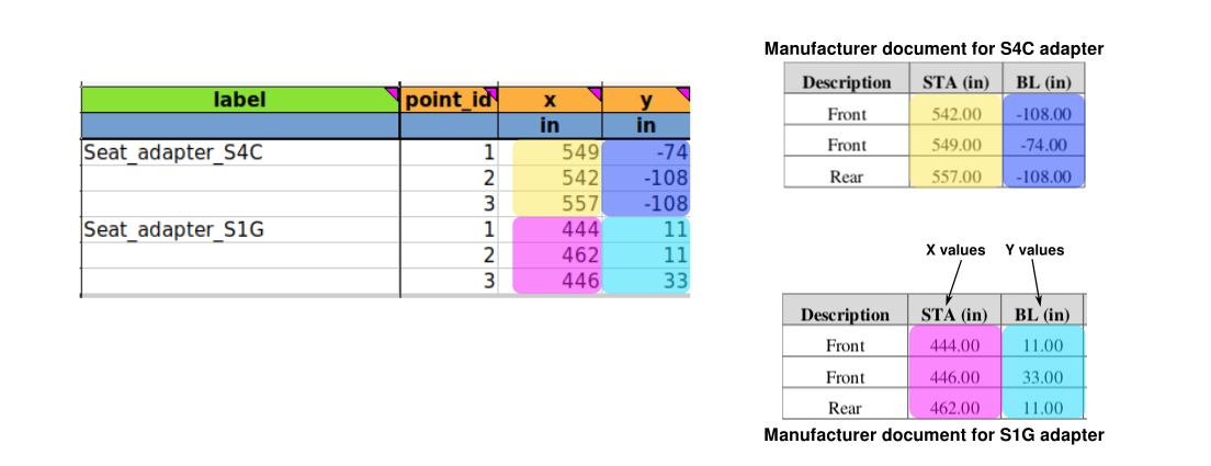
Fig. 96 Filling Business class seat adapter
As FTools always calculates the difference between each entered value in the X column and do the same with values in the Y column, it is possible to fill the sheet with absolute or relative coordinates, as we can see in Fig. 97. From the software point of view, the result will be the same.
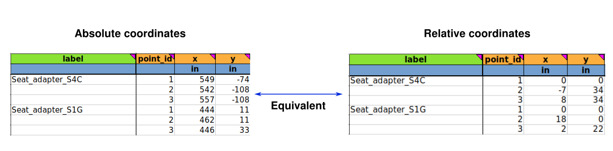
Fig. 97 Absolute entry vs relative entry
Note
You can fill the sheet with any coordinates, but to avoid making mistakes, it is better to use relative coordinates to minimise the number of geometry definition as most of the time many seats/items share the same geometry.
Furnitures
The way to fill the item_geom sheet for furniture is the same as the way to fill it for seats. The easiest way to complete the item_geom sheet is to enter all the interface points available in the furniture manufacturer’s documents for the furniture. See for example Fig. 98. Again, it is possible to fill the sheet by choosing absolute or relative coordinates.
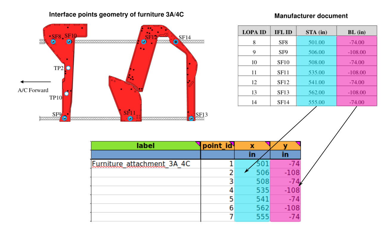
Fig. 98 Filling the item_geom sheet with a double furniture example
Note
The way to fill the item_geom sheet for a furniture that surrounds one seat is exactly the same.
canted fuselage section
The canted section is special because it is the zone where the aircraft rails are no longer parallel to the x-axis, but are at an angle. In this case it is strongly recommended to use absolute coordinates to fill the item_geom sheet for the item in question. FTools will automatically associate decimal “BL” values (Y column) with the nearest rail (example: if the BL value is -70.31 as it is for the seat S1A, FTools will place this interface point on the left side 74 rail in the canted section). See Fig. 99 for visualisation.
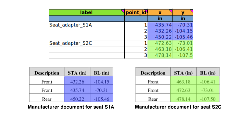
Fig. 99 Example of X and Y columns for seats installed in the canted section
Note
The way to fill the item_geom sheet for a canted section with furniture is exactly the same as it is for the seats.
item_asm sheet
The item_asm sheet is used to define the installation of the cabin item as specified in the LOPA. The item installation is limited to seat tracks. The sheet consists of several columns, which are visible in Fig. 100.
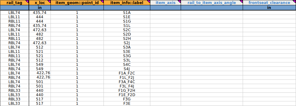
Fig. 100 First columns of the item_asm sheet for the business class seats and furniture
For the example, we will take up the seat 3A as we have seen in Fig. 91.
rail_tag column: it defines the seat rail on which the reference point of the item is located. These rails are described in Fig. 95.
x_loc column: it specifies the X location of the cabin item’s reference point. The reference point is one of the point_id that we can find on the item_geom sheet.
The Fig. 101 below are intended to show the user how to find information in the different sheets to fill in the rail_tag and x_loc columns.
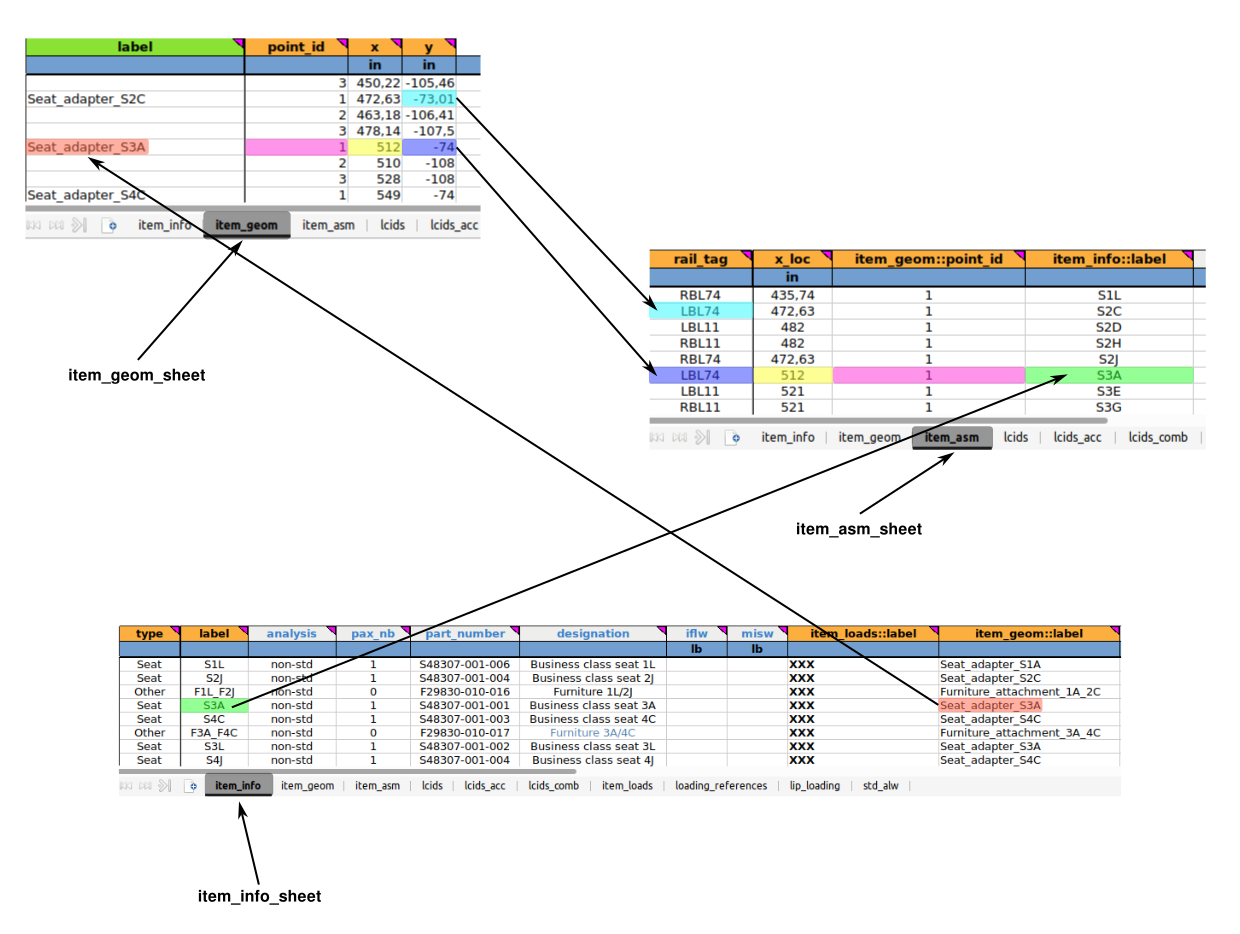
Fig. 101 Links between sheets
Note
We can also see on Fig. 101 the special case for seat 2C with decimal Y value in item_geom sheet. As we can see, in this case the user has to enter the nearest rail from the decimal value. Here we have -73.01, so the correct rail to associate is LBL74. Remember, all negative Y values are to the left of the aircraft cabin.
item_geom::point_id column: here the user must specify the ID of the selected point of the item interface. This is a cross-reference column with the item_geom sheet. As shown in Fig. 101, the point used for seat 3A is n°1 (pink highlight), but the user can choose any point he wants as a reference point. It is just important to keep a certain logic. This means that you have to pay attention to the rail_tag and select the one that corresponds to the chosen interface point. For example, if the user wants to select point_id n°2 for seat 2C, the rail_tag will no longer be LBL74 but LBL108.
Warning
For item that shares its interface points on a straight and a canted section, the reference point will have a significant impact on the seat position. See Sheet “item_asm” for better visualisation.
Note
For an item between a canted rail section and a straight rail section, it is preferable to choose a reference point on the straight rail. In our case, business class seats do not share a multiple rail configuration. Each element is either on a straight rail or on a canted rail.
item_info::label column: it defines the label of the cabin item. It is a cross reference to a label specified in the item_info sheet. It is possible to visualise the cross reference in Fig. 101 with green highlighting.
Note
Several lines can have the same label but not the same x_loc value because they can be in different rows. This is not the case for our business zone.
item_axis column: see Sheet “item_asm”: for full description. Not used in our example.
rail_to_item_axis_angle column: see Sheet “item_asm”: for full description. Not used in our example.
Note
These 2 columns will be useful during the part 2 of this tutorial for standard seats tutorial.
frontseat_clearance column: this column indicates the distance between a monument and a seat in the first row. See Sheet “item_asm” for full details. This column is only useful to fill in for a standard seat installation. Its use is explained in detail later in this tutorial in part 2 Part 2. Fill in the input file with Standard seats.
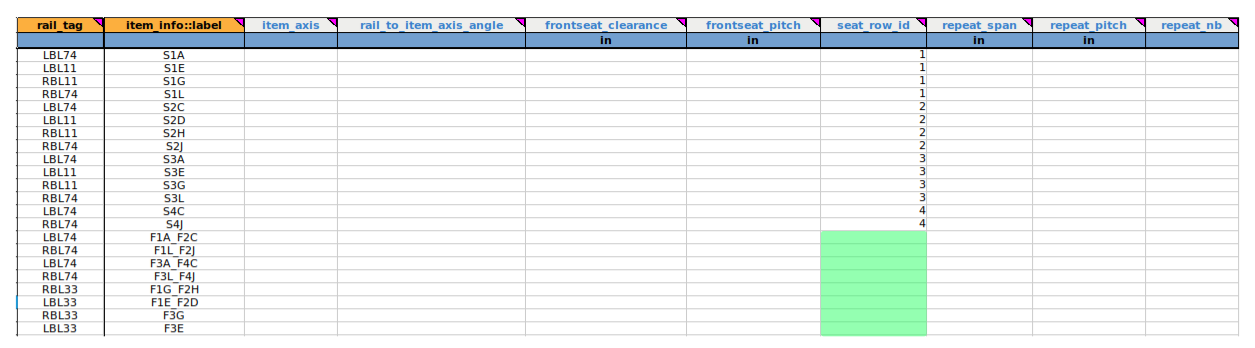
Fig. 102 Last columns of the item_asm sheet for the business class seats and furniture
frontseat_pitch column: this is the value of the “pitch” already calculated with the formula “X-4 + Xpivot”, taking into account the X that indicates the position of the seat in the first row. See Sheet “item_asm” for more details.
Note
The value of “frontseat_pitch” surpasses the default seat pitch automatically claculated. We therefore fill either the frontseat_clearance or the frontseat_pitch column.
seat_row_id column: specifies the row ID of the corresponding seat. It is only for seats and not for furniture as we can see in Fig. 102 where the green part is empty for the corresponding furniture.
For repeat_span, repeat_pitch and repeat_nb columns, as business class seats are all unique, this column will remain empty (as it is a non-mandatory value) and will be explained in detail in part 2 of tutorial 01 Part 2. Fill in the input file with Standard seats. Details of this column can be found in Sheet “item_asm”.
This is the end of part 1 of tutorial 01, here is the Excel sheet the user should get after filling all the zones 0:
Excel document completed for zone 0: ftools_ilbss_tpl_tuto01_z0.xlsx
At this moment, after running a new analysis on FTools, user should get the following cabin representation available in Fig. 103.
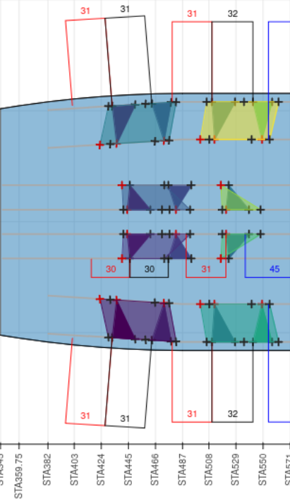
Fig. 103 Zone 0
User should have now the necessary knowledge to fill a LOPA’s Non Standard zone in FTools with any configuration he wants.
Part 2. Fill in the input file with Standard seats
Part 2 objectives: fill in the FTools’s spreadsheet for any Standard cabin configuration
Tutorial running time: TBD
ZONE 4
For this second part, we will focus our filling examples on zone 4 of the LOPA presented in Fig. 83, because this zone is composed of straight and canted rails (as it is, we will see the exception for standard seats in this zone). This zone consists entirely of Standard Economy seats. There are 130 seats with 11 different seat configurations as we can see in Fig. 105. The visualisation of the LOPA is available in Fig. 104 with seat numbers used to fill the spreadsheet.
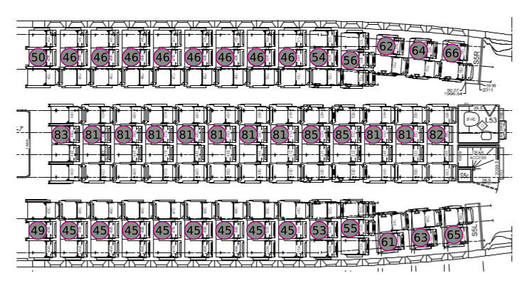
Fig. 104 Focus LOPA on zone 4 with Economy Class seats designation
The color code to illustrate the parallel between filling in the spreadsheet and the visual information of the LOPA is shown in Fig. 105 below.
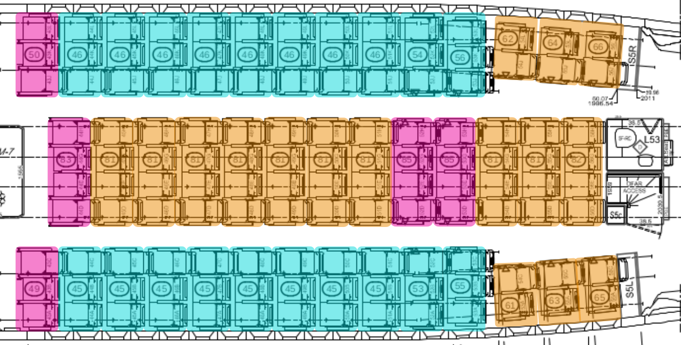
Fig. 105 Identification of seats to illustrate the parallel with the spreadsheet infos
Before starting with the standard seats part, it is important to know that, as mentioned before, we will focus our examples on zone 4 of the LOPA, but the user will have to fill in each zone to complete the full LOPA. Each zone paragraph is accompanied by a PDF document with all the information needed to fill in the spreadsheet. Here is the one for zone 4 below.
PDF document: Required_data_for_zone4.pdf
item_info sheet
All the following explanations are illustrated in the Fig. 106 and Fig. 107.
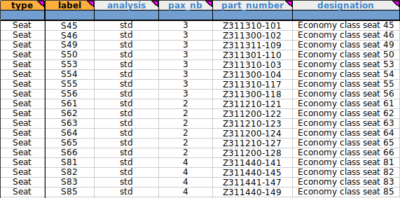
Fig. 106 First 6 columns of the item_info sheet for zone 4
type column: as we only have seats in this cabin area, we will put “Seat” for all seats installed in zone 4.
label column: the filling logic here is the same as before. We will fill “S” for seat followed by the seat number. For example, “S49” for seat number 49.
analysis column: as we are in a Standard seat configuration, the user must enter “std” for all seats installed in zone 4 to perform a standard analysis for these seats.
pax_nb column: unlike Business Class seats, the number of pax in Economy Class seats can vary between 2 and 4 pax. The user must select the correct pax number for the seat.
part_number column: in the same way as for the Business Class seat, the user can enter the item part number. This information is available in the seat manufacturer’s documentation. For the example, we have listed several part numbers in the item_info sheet, but this information is optional. For the following manipulation it does not matter if this field is left blank.
designation column: Here you must enter a text to describe the item. As this is a free text cell, you can enter any name you like. Here we choose the simplest way to name the items with “Economy class seat” followed by the seat number. However, a more common way is to name the seats as they are described in the manufacturer’s documentation.
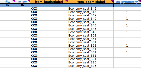
Fig. 107 Last 5 columns of the item_info sheet for zone 4
iflw column: we don’t need that column for this tutorial. As the identification code is white (optional) we will left this part blank. For more details, you can see Sheet “item_info”.
misw column: we don’t need to fill in this column but this weight will be used for seat row weight calculation in standard seat analyis. See Sheet “item_info” for more details.
item_loads::label column: as explained in the previous part about installing non-standard seats, this is a cross reference to the item_loads sheet. We don’t need this column for our tutorial, but as it is a mandatory field, we will just put “XXX” once in the “label” column in the item_loads sheet and for all lines in the item_info sheet. The way to do this is shown in Fig. 90.
item_geom::label column: it defines the label to be associated with the location of the interface points associated with the cabin seat or monument. This is a cross reference to the sheet “item_geom” which is filled in after the sheet “item_info”. Again, you can choose any name you like, but it is still better to choose one that is easy for the user to associate with references on the original LOPA.
Note
You can see that different seats can have the same item_geom::label. This is because these seats have the same geometry, and therefore it’s useless to enter the same geometry multiple times in the item_geom sheet (explained later). For example, this is the case for seats S61, S62, S63, S64, S65 and S66, which all have the same geometry as seat S61.
as_symmetry column : it indicates whether the associated interface load and geometry should be made symmetrical for the seat or monument. If this is the case, the user should enter ‘1’ in this field. As with the Business Class seat, some seats are symmetrical to each other. For example, this is the case for seats S49 and S50, but also for seats S45 and S46 or S53 and S54, so we put “1” in this column to indicate that these seats are symmetrical to each other (for these elements, FTools will invert the Y values but leave the X values unchanged).
Warning
This option can only be applied to seats or monuments that have the same interface load source and the same interface point geometry. This option will symmetrize both the load and the geometry. As we are focusing on geometry only in this tutorial, we will only look for geometry data in the seat manufacturer’s documents.
item_geom sheet
As shown in Fig. 94, the item_geom sheet is made up of 4 columns. In zone 4 of the LOPA we have 18 different seat references, but as you can see in Fig. 104, we only need to enter 5 of them in the item_geom sheet to fill all the item_geom::label columns in the item_info sheet. The 5 geometries we need are shown in Fig. 108 in Relative coordinate.
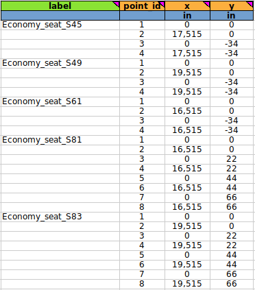
Fig. 108 item_geom sheet for zone 4
Warning
Before starting to describe each column, it is important to know that zone 4 is after the 2 added sections on the B777-300, which means that we have to add 210”+189” to each value read if the user chooses the Absolute coordinate. For more details see Fig. 93 and the explanations above.
label column: this column is linked to the item-info sheet. It must be entered as text, without spaces, with underscores. The tip is to choose a simple, easily recognisable name. For zone 4 we have chosen to fill it with the phrase “Economy_seat” followed by the seat number.
In zone 4, seats are disposed like this:
seat 50 is symmetric to seat 49
seat 46 is symmetric to seat 45
seats 54 and 56 are symmetric to respectively seats 53 and 55
seats 62, 64 and 66 are symmetric to respectively seats 61, 63 and 65
point_id column: in this column we specify the interface points of the item. It is possible to number the interfaces as you wish. Here we have chosen to number the interface points from 1 to 4 for 2-legged seats and from 1 to 8 for 4-legged seats. A global visualisation for easy numbering of seat interface points is available in Fig. 109.
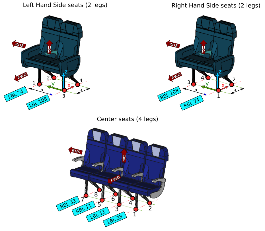
Fig. 109 Seats configurations
For the next part on how to fill in the X and Y values in Fig. 108, we will focus our example on seat S45 for the straight section and seat S61 for the canted section. All the following explanations are illustrated in Fig. 110 and Fig. 111.
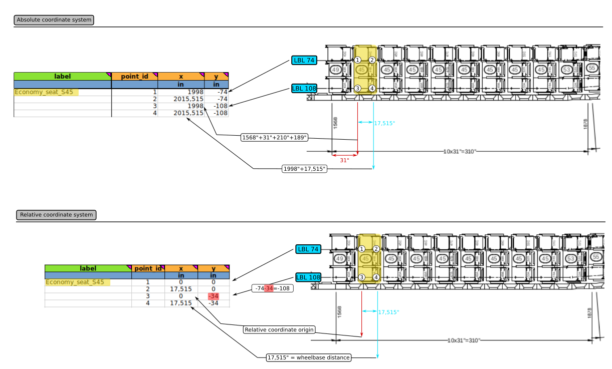
Fig. 110 Details about the filling procedure for seat S45 on item_geom sheet
There are 2 ways to fill in the item_geom sheet.The user can fill in seats values in Absolute or relative coordinates. Both example will be detailed. On the right side of the figure above we have the original LOPA with all the measurements on it. We can see that we have a repetition of the front interface points of seat S49 for 10 seats with a distance of 31” between 2 same interface points (red).
X column: as we can see, for the Absolute coordinate, the X values are the same for interface points 1 and 3 and the same for points 2 and 4. The values for points 1 and 3 are obtained by adding the reference value written on the LOPA (1568”), the 31” (distance of the front interface points of S45 compared to the front interface points of seat S49) and the distance of the 2 added sections (210”+189”). All the details of these sections are available in Fig. 93. As reference points 1 and 3 are aligned, they have the same X value. For the Relative coordinates, the origin of the benchmark is taken from the position of the points 1 and 3. This is why these points have for value 0.
Y column: the values in this column are associated with the rails on which the seats are installed. As described in Fig. 110, for Absolute coordinate, interface points 1 and 2 are on the inboard left side rail (74) and interface points 3 and 4 are on the outboard left side rail (108). For Relative coordinate, origin of the benchmark is set on interface point n°1. So, points 1 and 2 are on the same rail so they share the same Y value. Point 3 and 4 are on the rail LBL108 so their relative coordinates are at -34” from the rail LBL74 (red highlight in Fig. 110).
Note
Reminder: The values in the Y column are preceded by a “-” because these rails are on the left side of the aircraft cabin.
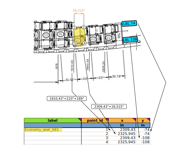
Fig. 111 Details about the filling procedure for seat S61 on item_geom sheet
As described in Fig. 111, the filling procedure is identical to that for the S45. Even in the canted section, you must enter the same rails as in the straight section. FTools knows how to deal with this zone. From a certain X position, it will automatically set the seat on the nearest rail.
Note
For this situation (canted section), as we are taking the original LOPA as a model, Absolute coordinates are highly recommended.
item_asm sheet
The item_asm sheet is used to define the installation of the cabin item as specified in the LOPA. The item installation is limited to seat tracks. The sheet consists of several columns, which are visible in Fig. 112.
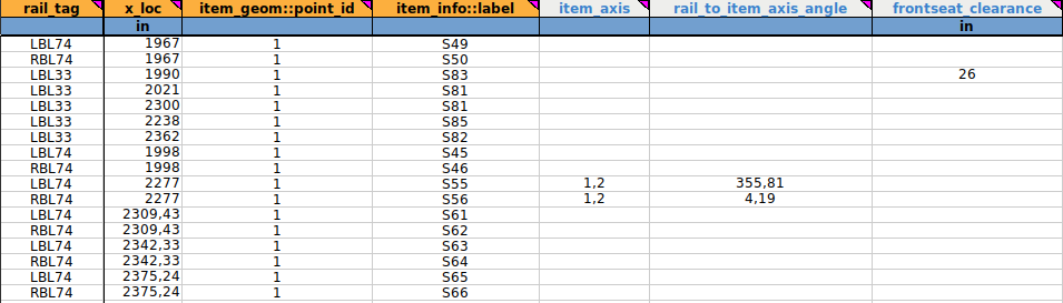
Fig. 112 First 7 columns of the item_asm sheet
rail_tag column: it defines the seat rail on which the reference point of the object is located. These rails are described in Fig. 95.
x_loc column: it specifies the X location of the cabin item’s reference point. The reference point is one of the point_id that we can find on the item_geom sheet.
The Fig. 113 below shows the user how to find information in the different sheets to fill the rail_tag and x_loc columns.
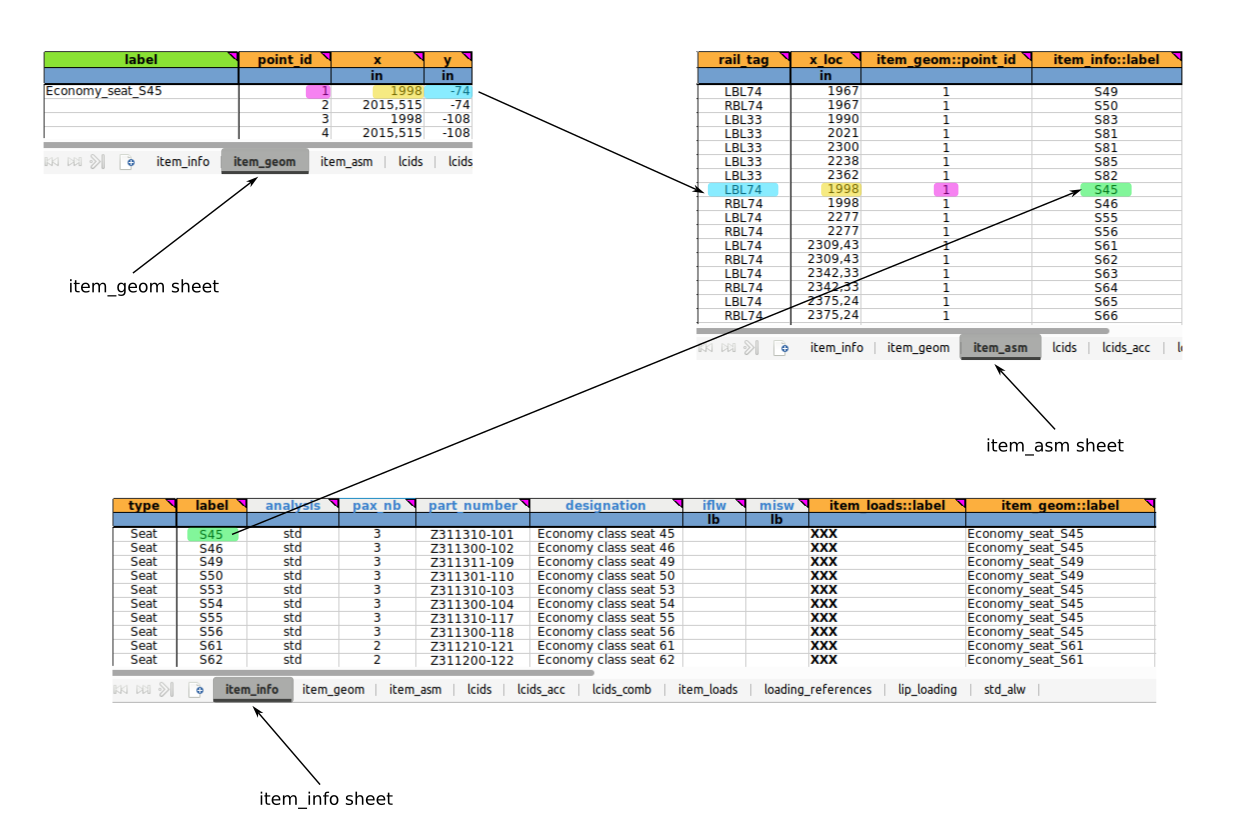
Fig. 113 Links between sheets
item_geom::point_id column: it is a cross-reference to the item_geom sheet. The user must specify the ID of the selected point of the item interface. For our example with the S45 seat, we have chosen point n°1 (highlighted in pink), but it is important to know that you can choose any point. It is just important to follow a certain logic.
Warning
For seats between a straight and a canted section, the chosen reference point will have a significant impact on the seat orientation, this is the case in our area for seats S53 and S54. We will see later how to deal with this orientation manually (for seats S55 and S56).
item_info::label column: it defines the label of the cabin item. It is a cross reference to a label specified in the item_info sheet. This cross-reference can be seen in Fig. 113 (highlighted in green).
item_axis column: see Sheet “item_asm”: for full description. This column is linked with the column rail_to_item_axis_angle.
rail_to_item_axis_angle column: see Sheet “item_asm”: for full description. This column is linked with the column item_axis.
These 2 columns are suitable for seats S55 and S56. These seats are positioned on canted rails, but the seats are straight like seats on straight rails. All the following explanations are illustrated in Fig. 114.
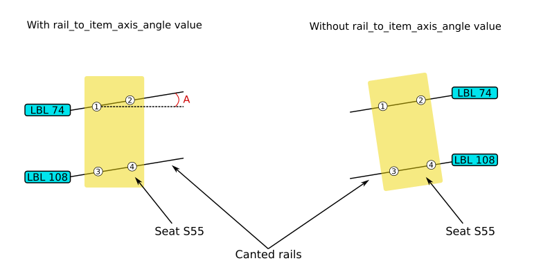
Fig. 114 axis angle tips for canted section
The item_axis column is here to define an axis for the rotation value that we will set in the rail_to_item_axis_angle column for the item in question. As we can see in Fig. 112, for seat S55 we have “1,2” in the item_axis column. This defines the direction of the vector for the rotation. As point 1 is the origin of our vector and also our reference point, the rotation will take place around this point. The visual representation of this entry is available in Fig. 115.
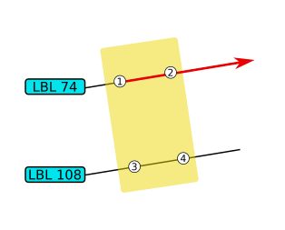
Fig. 115 explanation for vector direction
As shown in Fig. 114, angle A is the angle between the X-axis of the plan and the inclined rail. The value in the rail_to_item_axis_angle column is the angle required to align the seat with the aircraft X-axis. According to the measurements, the required angle value is 4.19° (for seat S56). As seat S55 is symmetrical to seat S56, the angle value for S55 is the complement, i.e. 355.81°.
Warning
Angle values must be positive and between 0 and 360 degrees. Angle rotation are always applied in an anti-clockwise direction.
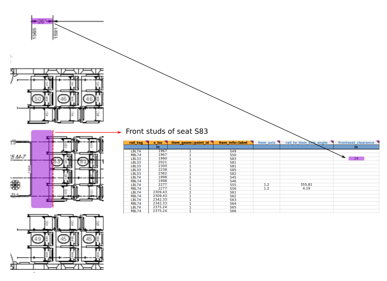
Fig. 116 frontseat_clearance value
frontseat_clearance column: it specifies the clearance between a monument and a seat in the front row. The clearance value corresponds to the distance between the front stud of the seat in question and the AFT monument/wall. This column is not mandatory, but it can be very useful to visualise all the details on the FTools LOPA as well as possible. We can have an example with the seat S83 on Fig. 112 with 26” as frontseat_clearance. Fig. 116 is here to show where to find the info on the original LOPA.
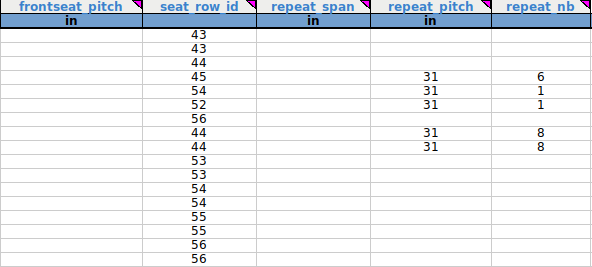
Fig. 117 Last 5 columns of the item_asm sheet
frontseat_pitch column: for further details, please refer to Sheet “item_asm” section.
Note
The value of “frontseat_pitch” surpasses the default seat pitch automatically claculated. We therefore fill either the frontseat_clearance or the frontseat_pitch column.
That is why we only have the S83 seat with a value in the frontseat_clearance column and not in the frontseat_pitch column (other front seats have no monument in front of them).
seat_row_id column: it specifies the row ID of the corresponing seat. Visual representation are available in Fig. 118.
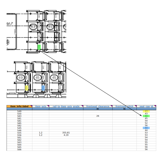
Fig. 118 seat row value
repeat_span column: it specifies the span used for the repetition of the item installation. This field should be used in combination with the field repeat_pitch or repeat_nb to specify multiple installation of one cabin item.
repeat_pitch column: it specifies the pitch used for the repetition of the item installation. This field should be used in combination with the field repeat_nb or repeat_span to specify multiple installation of one cabin item.
repeat_nb column: it specifies the number of repetitions used for the repetition of the item installation. This field should be used in combination with the field repeat_pitch or repeat_span to specify multiple installation of one cabin item.
Warning
Only 2 of the 3 preceding columns need to be filled in. See Fig. 119 for an example and Fig. 120 for more details.
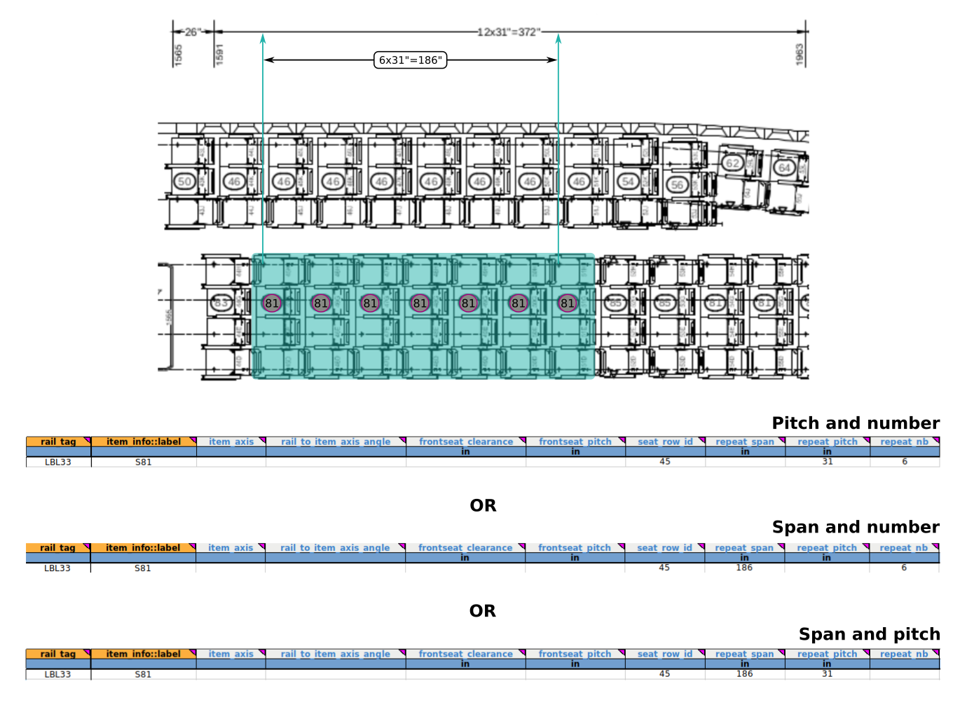
Fig. 119 Visualisation for different entries for span, pitch and number infos
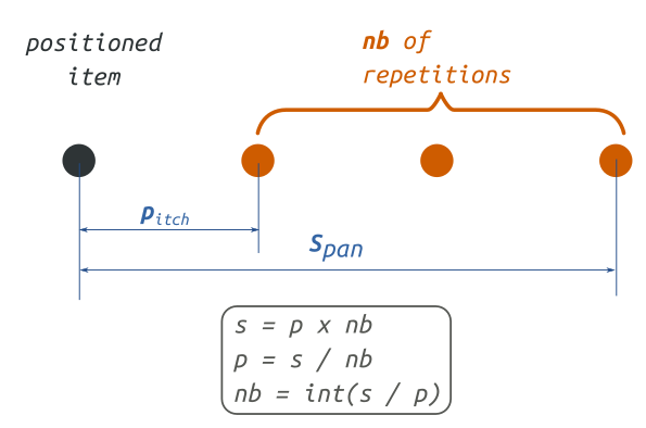
Fig. 120 Details about the repetition parameters
This is the end of the zone 4 of the Part 2 of the tutorial 01. Here is the Excel sheet user should get after filling in all the zone 4 :
Excel document completed for zone 0: ftools_ilbss_tpl_tuto01_z4.xlsx
At this moment, after running a new analysis on FTools, user should have the following cabin representation available in Fig. 121.
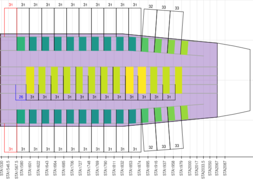
Fig. 121 Zone 4
Now, user should have the necessary knowledge to fill a LOPA’s Standard zone in FTools with any configuration he wants.
Zone 1
Based on Part 2. Fill in the input file with Standard seats, the user has to practise to fill the whole zone 1 in the FTools spreadsheet. Here is the visualisation of the LOPA in Fig. 122 with seat numbers that will be used to fill the spreadsheet.
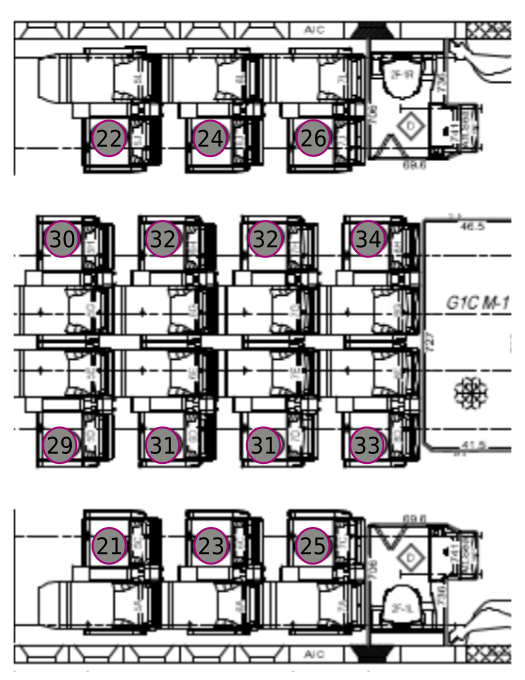
Fig. 122 Focus LOPA on zone 1 with premium economy class seats designation
The color code to illustrate the parallel between filling in the spreadsheet file and the LOPA’s visual information is presented in Fig. 123.
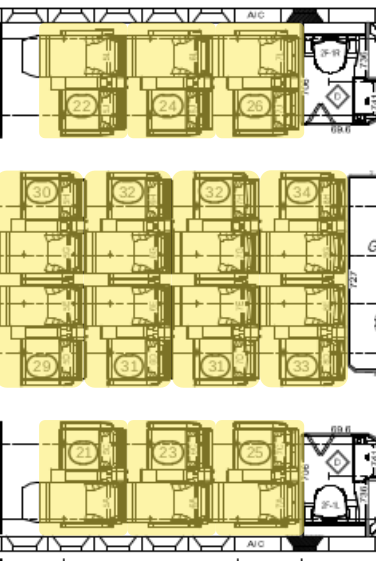
Fig. 123 Identification of seats to illustrate the parallel with the spreadsheet infos
Here is the PDF document with all informations needed to fill in the zone 1:
PDF document: Required_data_for_zone1.pdf
Here is the Excel sheet user should get after filling in all the zone 1:
Excel document: ftools_ilbss_tpl_tuto01_z1.xlsx
After running a new analysis on FTools, user should have the following cabin representation available in Fig. 124.
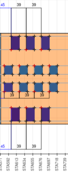
Fig. 124 Zone 1
Zone 2
Based on Part 2. Fill in the input file with Standard seats, the user will have to practise to fill the whole zone 2 in the FTools spreadsheet. Here is the visualisation of the LOPA in Fig. 125 with seat numbers that will be used to fill the spreadsheet.
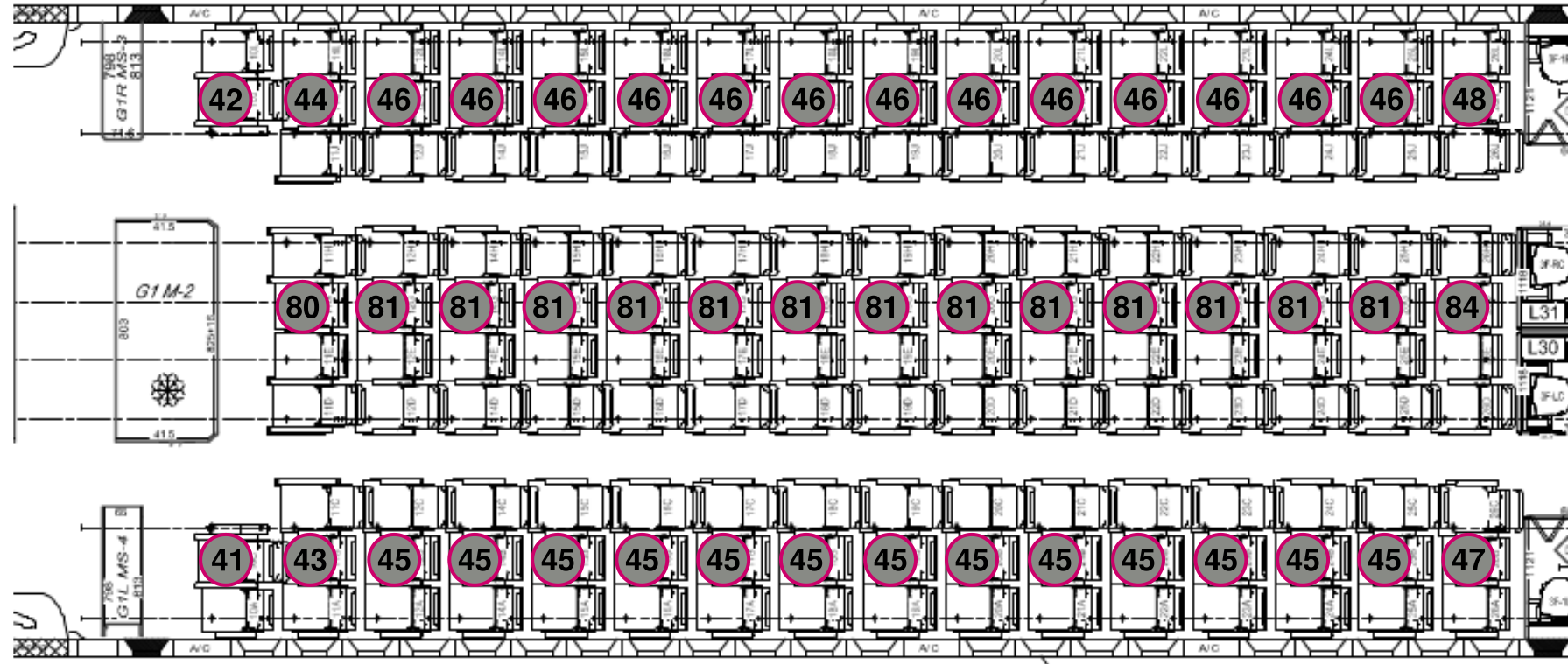
Fig. 125 Focus LOPA on zone 2 with premium economy class seats designation
The color code to illustrate the parallel between filling in the spreadsheet file and the LOPA’s visual information is presented in Fig. 126.
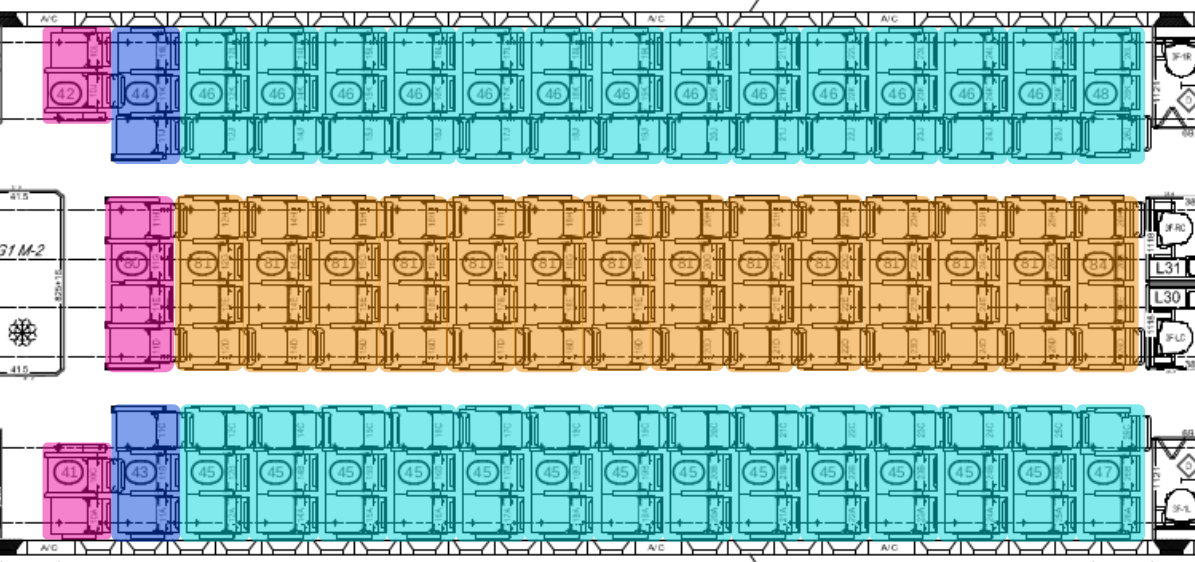
Fig. 126 Identification of seats to illustrate the parallel with the spreadsheet infos
Here is the PDF document with all informations needed to fill in the zone 2:
PDF document: Required_data_for_zone2.pdf
Here is the Excel sheet user should obtain after filling in all the zone 2:
Excel document: ftools_ilbss_tpl_tuto01_z2.xlsx
After running a new analysis on FTools, user should have the following cabin representation available in Fig. 127.
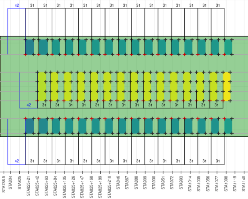
Fig. 127 Zone 2
Zone 3
Based on Part 2. Fill in the input file with Standard seats, the user has to practise to fill the whole zone 3 in the FTools spreadsheet. Here is the visualisation of the LOPA in Fig. 128 with seat numbers that will be used to fill the spreadsheet.
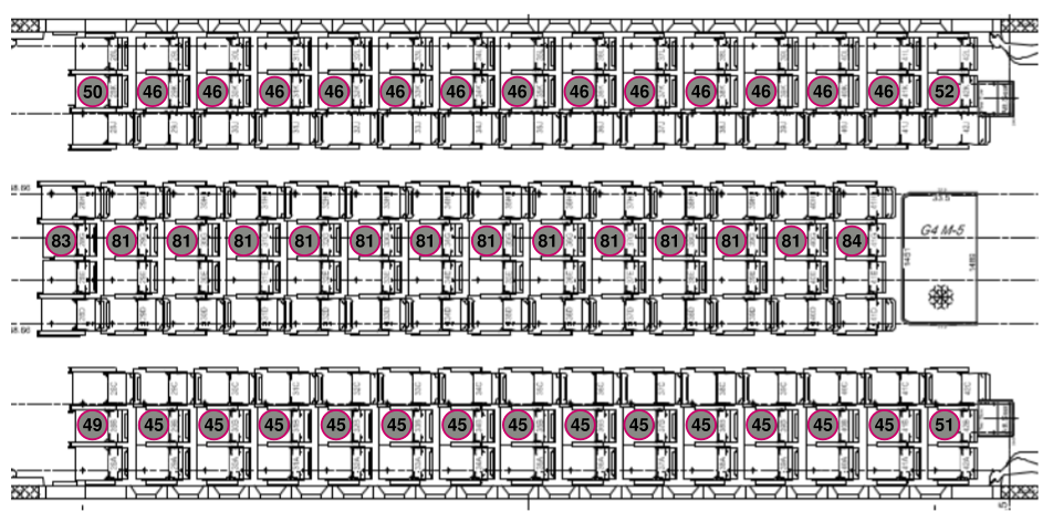
Fig. 128 Focus LOPA on zone 3 with premium economy class seats designation
The color code to illustrate the parallel between filling in the spreadsheet file and the LOPA’s visual information is presented in Fig. 129.
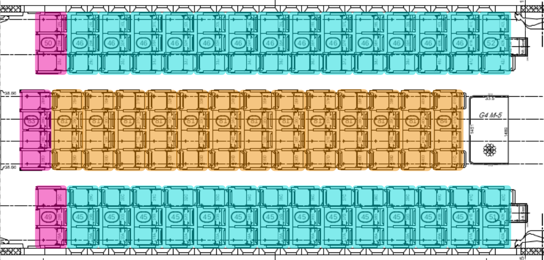
Fig. 129 Identification of seats to illustrate the parallel with the spreadsheet infos
Here is the PDF document with all informations needed to fill in the zone 3:
PDF document: Required_data_for_zone3.pdf
Here is the Excel sheet user should obtain after filling in all the zone 3:
Excel document: ftools_ilbss_tpl_tuto01_z3.xlsx
After running a new analysis on FTools, user should have the following cabin representation available in Fig. 130.
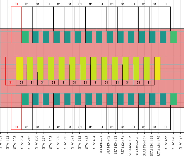
Fig. 130 Zone 3
This is the end of the tutorial 01. For now, user must have the necessary knowledge to enter a complete LOPA with any configuration he wants from non-standard seats to standard seats.