Non Std XLSX output
Warning
THIS SECTION (source/nonstd_output.rst) is to be deleted once its data will be
rewritten to source/checkers_and_analysis.rst
Bar analysis output
This is a seven sheets spreadsheet generated to summarize key analysis data regarding bar bending moment or shear force comparative analysis:
beam_properties: sheet summarizing mechanical properties of all FE BAR elements of relevant structural item (ie: seat track, cross beam or Overwing beam)
all_allowable: sheet used to present allowable from each reference loading for all different mechanical properties
allowable: sheet summarizing the highest allowable for each different mechanical property
MS: main sheet presenting Margin of Safety calculation for all BAR elements of relevant structural item
_crits_pre: pre-selection of the most critical margin of safety per structural element
critical_beams_envelope: sheet used to present the lowest margin of safety
MS_reduced: sheet used to present a summary of the lowest margins of safety
Note
Units are not specified in this spreadsheet. Values presented are in the unit system of the analysis.
“beam_properties” Sheet
Before going into the output details presented in this sheet it is important to understand its overall structure.
“all_allowable” Sheet
Before going into the output details presented in this sheet it is important to understand its overall structure. As shown on Fig. 62 this sheet presents allowable for cross beams and seat tracks. For each Reference loading previously selected by the end user (see Running a new analysis Step #2/3: Zones selection), key data are presented.
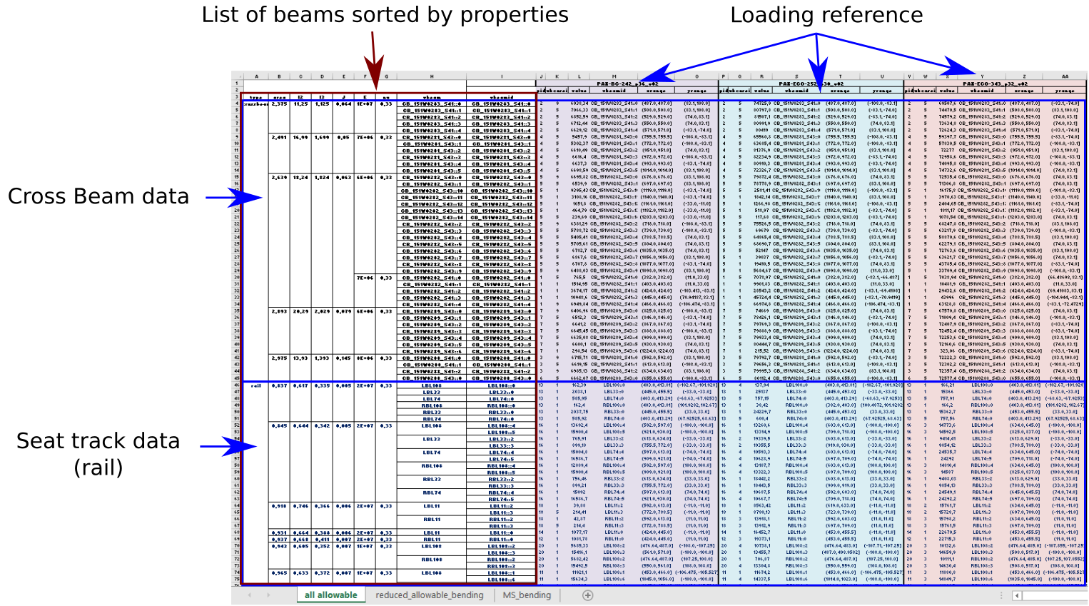
Fig. 62 “all allowable” sheet overview
beam properties and identifcation
type: crossbeam or rail
area, I2, I3, J, E, nu: mechanical properties of the beam. Respectively its cross sectional area, section inertia around its axis, torsional constant, Material Young modulus and Poisson’s ratio.
vbeam, vbeamid: virtual beam label and its instance. For cross beam, each instance is a cross beam itself. Whereas for rail, a virtual beam is made of several instances. For more information on virtual beams see Concept of virtual beam (vbeam)
finite element results with reference loading selected
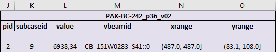
Fig. 63 reference loading allowable output (sheet “all allowable”)
pid: property ID associated to the beam
subcaseid: subcase ID of the load case providing the highest bending moment on the beam
Warning
The list of subcases is specific to each Reference loading and it doesn’t correspond to the list of subcases defined by the en user for the installation being checked.
value: maximum bending moment reached on the beam at node A or B
vbeamid: ID of the virtual beam
xrange: range in X of the finite element belonging to the virtual beam on which the maximum bending moment has been reached.
yrange: range in Y of the finite element belonging to the virtual beam on which the maximum bending moment has been reached.
Note
for cross beam the xrange indicates its location. For instance a range (1140, 1140] indicates that the cross beam is located at X=1140.0 inch in the aircraft coordinate system (see Fig. 38).
Warning
Cross beam location is defined in aircraft coordinate system. It shouldn’t be mixed with Boeing station (for instance X=1140in is equivalent to STA930)
“allowable” sheet
The overall structure of this sheet is presented on the Fig. 64
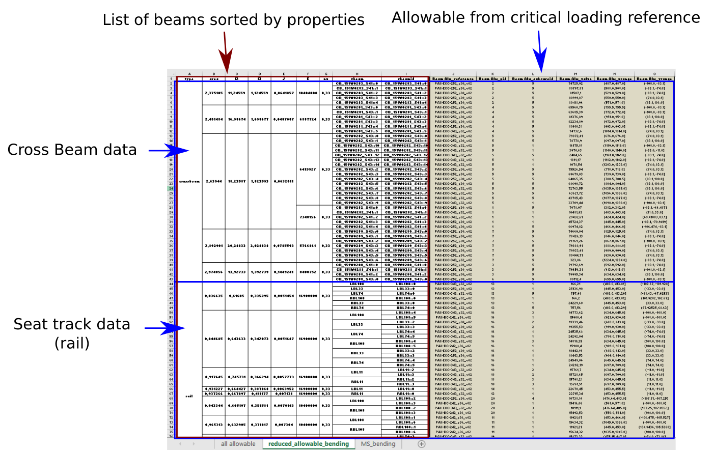
Fig. 64 “reduced_allowable_bending” sheet overview
beam properties and identifcation
type: crossbeam or rail
area, I2, I3, J, E, nu: mechanical properties of the beam. Respectively its cross sectional area, section inertia around its axis, torsional constant, Material Young modulus and Poisson’s ratio.
vbeam, vbeamid: virtual beam label and its instance. For cross beam, each instance is a cross beam itself. Whereas for rail, a virtual beam is made of several instances. For more information on virtual beams see Concept of virtual beam (vbeam)
finite element results on most critical beam with Reference loading

Fig. 65 enveloppe of reference loading allowable
Beam Alw_reference: identification of the standard seating configuration used for reference loading providing the highest bending moment on the beam
Beam Alw_pid: property ID of the corresponding beam
Beam Alw_subcaseid subcase ID of the load case providing the highest bending moment on the corresponding reference loading
Beam Alw_value: value of the highest bending moment reached on the beam of the corresponding reference loading
Beam Alw_xrange: range in X direction of the finite element belonging to the virtual beam on which the maximum bending moment has been reached with the corresponding reference loading
Beam Alw_yrange: range in Y direction of the finite element belonging to the virtual beam on which the maximum bending moment has been reached with the corresponding reference loading
“MS_bending” sheet
The overall structure of this sheet is presented on the Fig. 66
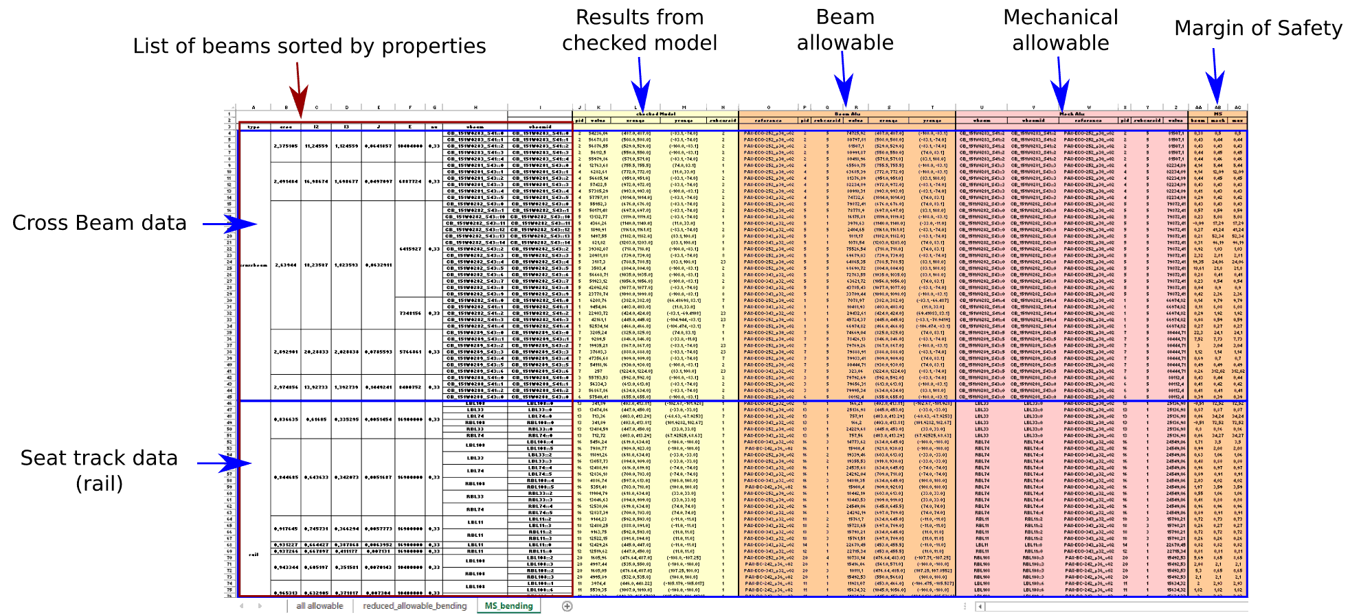
Fig. 66 “MS_bending” sheet overview
beam properties and identifcation
type: crossbeam or rail
area, I2, I3, J, E, nu: mechanical properties of the beam. Respectively its cross sectional area, section inertia around its axis, torsional constant, Material Young modulus and Poisson’s ratio.
vbeam, vbeamid: virtual beam label and its instance. For cross beam, each instance is a cross beam itself. Whereas for rail, a virtual beam is made of several instances. For more information on virtual beams see Concept of virtual beam (vbeam)
finite element results on checked model
The checked model is the finite element model of the selected floor structure configuration (see Running a new analysis Step #1/3: Validation of Loading input file) loaded with interface load of the installation to be checked (see Running a new analysis Step #2/3: Zones selection).
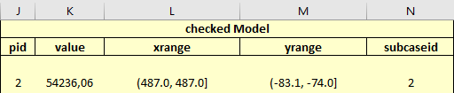
Fig. 67 results on beam of checked model
pid: property ID of the corresponding beam
value: value of the maximum bending moment reached on the beam at node A or B
xrange: range in X direction of the finite element belonging to the virtual beam on which the maximum bending moment has been reached with the user defined loading
yrange: range in Y direction of the finite element belonging to the virtual beam on which the maximum bending moment has been reached with the user defined loading
subcaseid: load case ID corresponding to the list of load cases provided in the Loading file (see Sheet “lcids”)
beam allowable from Reference loading
The 6 columns underneath “Beam Alw” correspond exactly to the results columns of the “reduced_allowable_bending” sheet. They present the maximum bending moment reached on the beam with one of the Reference loading. This value is considered as the allowable for the beam itself.
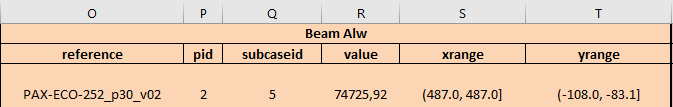
Fig. 68 beam allowable from reference loading
allowable from a beam of the same property ID
The 6 columns underneath “Mech Alw” summarize the maximum bending moment reached on one beam among all beams sharing the same mechanical properties (same pid).
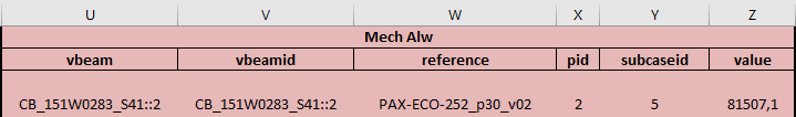
Fig. 69 mechanical allowable from reference loading
vbeam: virtual beam
vbeamid: virtual beam ID
- reference: identification of the standard seating configuration used for reference loading providing the highest bending moment on a beam
among all beams sharing the same mechanical properties (same pid)
pid: beam property ID
subcaseid: load case ID of the corresponding Reference loading
value: bending moment reached on one beam among all beams sharing the same mechanical properties (same pid)
Margin of Safety
Two different Margin of Safety are calculated and their maximum of is presented
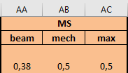
Fig. 70 Margin of Safety
- beam: the MS calculated in this column is based on a “beam to beam” comparison.
The maximum bending moment reached on this beam is compared to the maximum allowable from a Reference loading reached on the same beam. \(MS_{beam}=\frac{value~of~col~R}{value~of~col~K}-1\)
- mech: the MS calculated in this column is based on a comparison between all beams of same mechanical properties.
The maximum bending moment reached on this beam is compared to the maximum allowable reached on a beam of same mechanical properties. \(MS_{mech}=\frac{value~of~col~Z}{value~of~col~K}-1\)
max: the maximum Margin of Safety of the two MS calculated is presented here.
Note
Margin of Safety calculated here are relative MS as they compare two values, one from a reference loading (valid PAX seating configuration) and one from the installation to be checked.
Seat tracks and Cross beams Shear
This spreadsheet is a three sheets generated to summarize keys analysis data regarding cross beam and seat tracks shear force.
See “MS_bending” sheet for a detailed presentation of this spreadsheet as they share the exact same structure. Only the output value “bending moment” is replaced by “shear force”