Running a new analysis
A new analysis can be triggered by selecting Create a New Analysis under the menu My analysis.
To perform an analysis the following 3 steps should be followed:
Validation of the Loading Input Data and selection of the associated aircraft floor structure (fsconf)
Selection of cabin LOPA zone to analyse
Selection of standard seating configuration reference loading (Non-Standard seat installation) and installation effectivity
Step #1/3: Validation of Loading input file
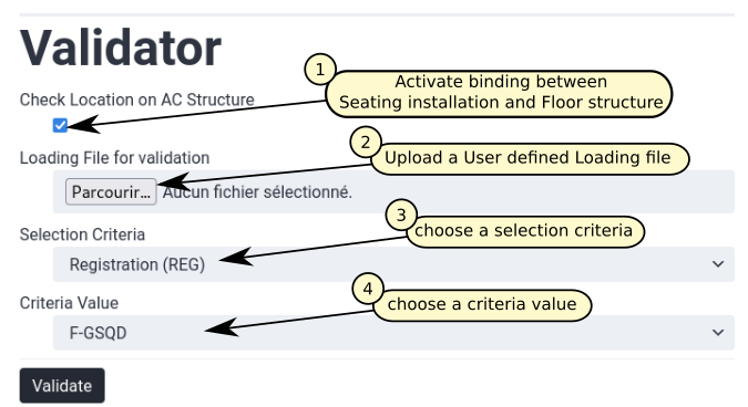
Fig. 19 New analysis Step #1/3
Check Location on AC Structure
This option enables the visualisation of the seats and cabin monuments installation on a selected floor structure.
If this option is not selected, the Loading Input Data is only checked in a stand alone mode:
validation of entry against required data format (see Column header color code)
validation of entered field data type (see Field data type)
validation of sheets cross reference (see Understanding sheets cross references)
When this option is validated, the installation of each seat and monument on seat track is checked. As a result of this deep validation two different views of the cabin LOPA are presented. A first one is presenting the seat pitch associated with each standard seat. A second one, is presenting all seats / monuments with their ‘label’ indicated (see Sheet “item_info” for more information on cabin seat / monument label definition). Additionally, the seating zones on the cabin LOPA is highlighted on this second view.
On both views, seat row number as entered in Sheet “item_asm” is presented with also a ruler indicating aircraft stations.
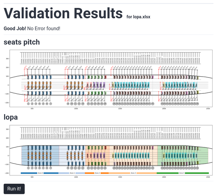
Fig. 20 Presentation of validation results
Uploading Loading file
The Loading Input Data of the installation to justify needs to be entered in the FTools at this stage. This file defines all seats and monument installed on the cabin LOPA with their associated Interface Load (IFL).
Templates of the Loading file can be downloaded in the Resources section of the FTools.
For more information on this spreadsheet please refer to Loading Input Data
Selection of the floor structure configuration
The selection of the floor structure configuration is required for the justification of Non-Standard seat installation. For Standard seat installation only the selection of the aircraft type is required (standard seat justification is independent of aircraft floor structure configuration as it is based on OEM allowable comparison).
The structural substantiation of the non standard seating installation is based on a Finite Element model of the floor structure. As all aircraft of a kind don’t necessarily share the same floor structure configuration, variation in some structural element (mainly seat tracks) needs to be taken into account to properly reflect floor structure stiffness and strength.
When running a new analysis integrating Non-Standard seat installation the first point to clarify is the floor structure configuration. The following flowchart provides some guidance for the selection of the appropriate floor structure configuration.
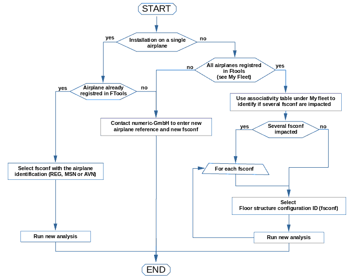
Fig. 21 Floor structure configuration selection flowchart
Note
As presented in the above flowchart if the installation to justify impact several floor structure configurations, an analysis per configuration needs to be performed.
Step #2/3: Zones selection
At this stage, the coverage of the analysis and reporting needs to be defined. When a cabin LOPA is entered in the Loading Input Data, seating zones are automatically detected based larger gap between seats / monument installation. The list of detected zones are presented and can be selected to trigger their substantiation. In this window, another key information is displayed: for each zone the detection of Non-Standard seat installation is indicated. When a Non-Standard seat installation is identified in a zone, a non-std analysis is required for this zone.
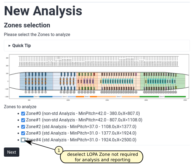
Fig. 22 New analysis Step #2/3
Step #3/3: References & Effectivity
At this step, loading reference required to pass Non-Standard seat installation by comparison should be selected along with the seating installation effectivity. If only standard seat installation analysis has been requested in previous step, selection of loading reference is not required and ticking box are not displayed.
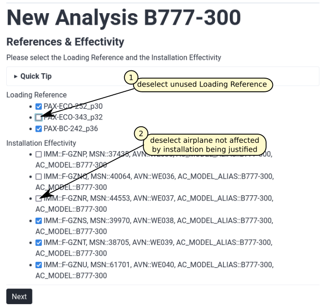
Fig. 23 New analysis Step #3/3
Selection of loading reference
Once the appropriate floor structure configuration has been selected, one or more standard seating installation should be selected.The corresponding interface loads for the most critical load cases and Passenger Occupancy Combination (POC) will be automatically applied on the floor structure FE model.
In the current software version six loading references can be selected:
PAX-BC-242_p36-00: standard business class seating configuration with 2 outboard double seats and a central quad seat installed at a pitch of 36 inches
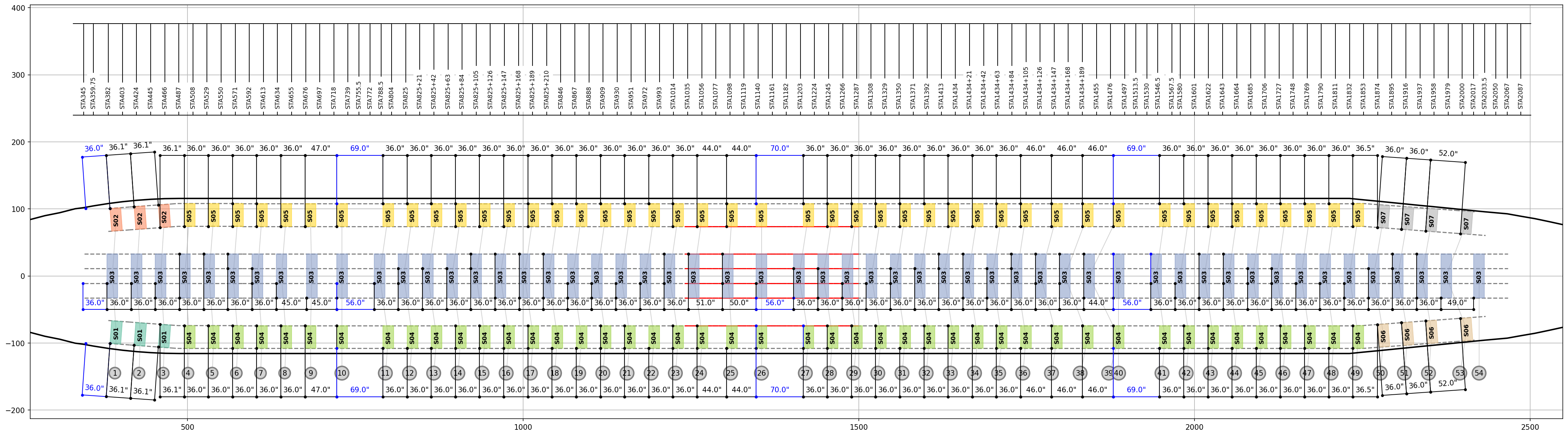
Fig. 24 Reference seating configuration, PAX BC 2-4-2, seat pitch=36in
The following load cases have been implemented for this seating configuration:
LCID |
Load Case Title |
QUAD Seat POC |
DBL Seat POC |
|---|---|---|---|
1 |
TTL 9g FWD |
1111 |
11 |
2 |
TTL 9g FWD |
0111 |
10 |
3 |
TTL 9g FWD |
1110 |
01 |
4 |
TTL 9g FWD |
1010 |
11 |
5 |
TTL 6.2g DOWN |
1111 |
11 |
6 |
TTL 6.2g DOWN |
0111 |
10 |
7 |
TTL 6.2g DOWN |
1110 |
01 |
8 |
TTL 6.2g DOWN |
1010 |
11 |
9 |
TTL 4g RHS |
1111 |
11 |
10 |
TTL 4g RHS |
0111 |
10 |
11 |
TTL 4g RHS |
1110 |
01 |
12 |
TTL 4g RHS |
1010 |
11 |
PAX-BC-242_p42-00: standard business class seating configuration with 2 outboard double seats and a central quad seat installed at a pitch of 42 inches
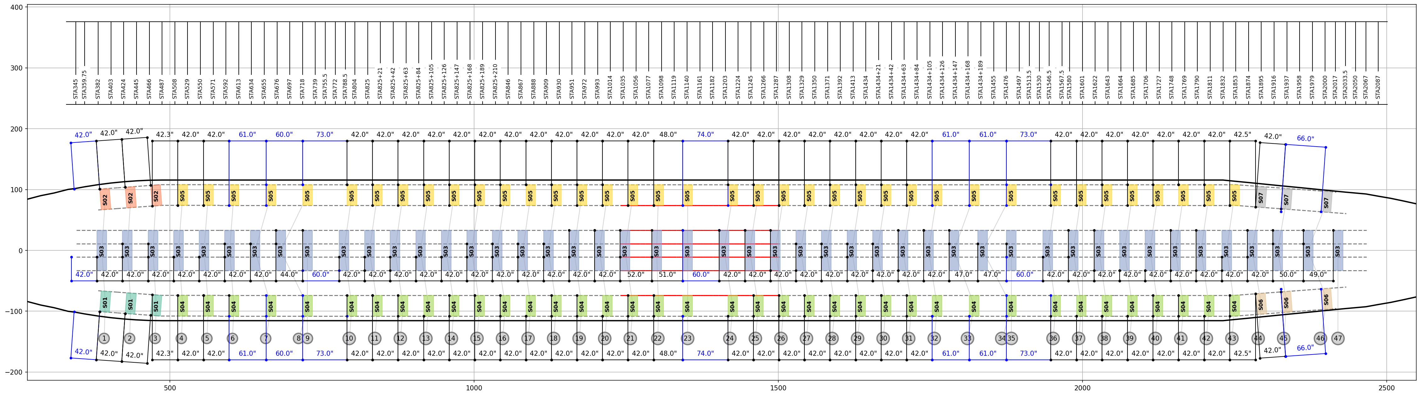
Fig. 25 Reference seating configuration, PAX BC 2-4-2, seat pitch=42in
The same load cases as the PAX Business Class 2-4-2 with a seat pitch of 36in have been implemented for this Reference seating configuration.
PAX-ECO-252_p30-00: standard economy class seating configuration with 2 outboard double seats and a central quint seat installed at a pitch of 30 inches (First LOPA variant)
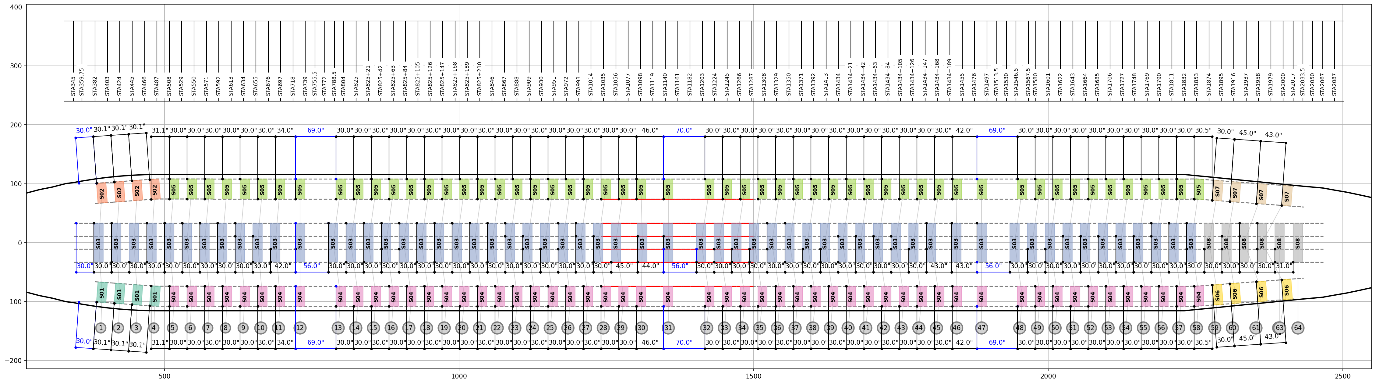
Fig. 26 Reference seating configuration, PAX ECO 2-5-2, seat pitch=30in (First LOPA variant)
The following load cases have been implemented for this seating configuration:
LCID |
Load Case Title |
QUINT Seat POC |
DBL Seat POC |
|---|---|---|---|
1 |
TTL 9g FWD |
11111 |
11 |
2 |
TTL 9g FWD |
01011 |
10 |
3 |
TTL 9g FWD |
01101 |
01 |
4 |
TTL 9g FWD |
01001 |
11 |
5 |
TTL 6.2g DOWN |
11111 |
11 |
6 |
TTL 6.2g DOWN |
01011 |
10 |
7 |
TTL 6.2g DOWN |
01101 |
01 |
8 |
TTL 6.2g DOWN |
01001 |
11 |
9 |
TTL 4g RHS |
11111 |
11 |
10 |
TTL 4g RHS |
01011 |
10 |
11 |
TTL 4g RHS |
01101 |
01 |
12 |
TTL 4g RHS |
01001 |
11 |
PAX-ECO-252_p30-01: second LOPA variant of the Reference seating configuration PAX ECO 2-5-2. In each seating zone, front row seats have been shifted by 5in AFT.
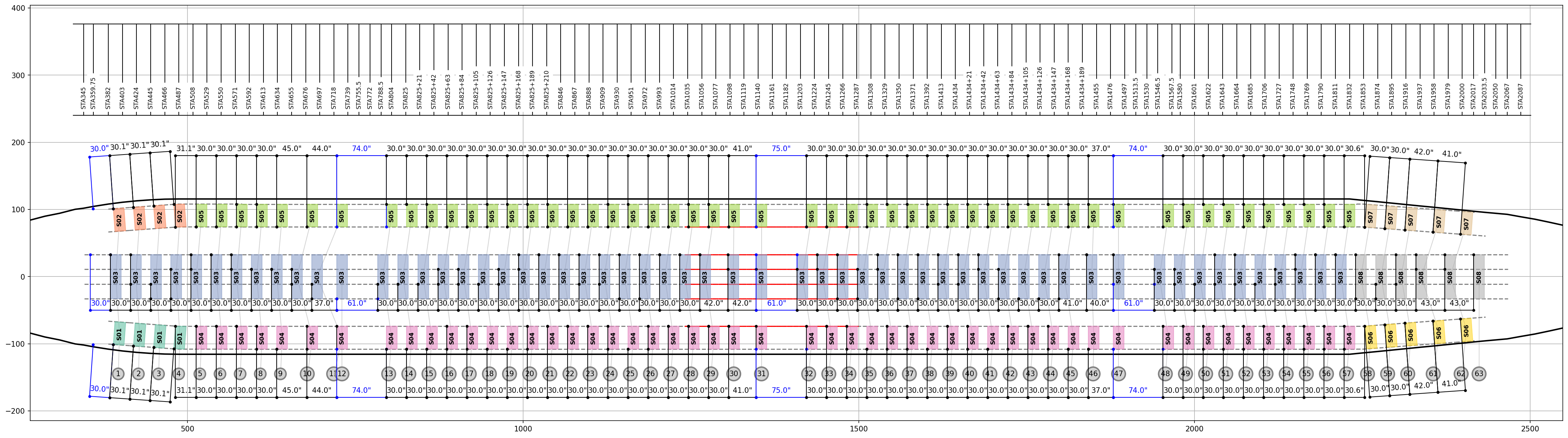
Fig. 27 Reference seating configuration, PAX ECO 2-5-2, seat pitch=30in (Second LOPA variant)
PAX-ECO-252_p30-02: third LOPA variant of the Reference seating configuration PAX ECO 2-5-2. In each seating zone, front row seats have been shifted by 10in AFT.
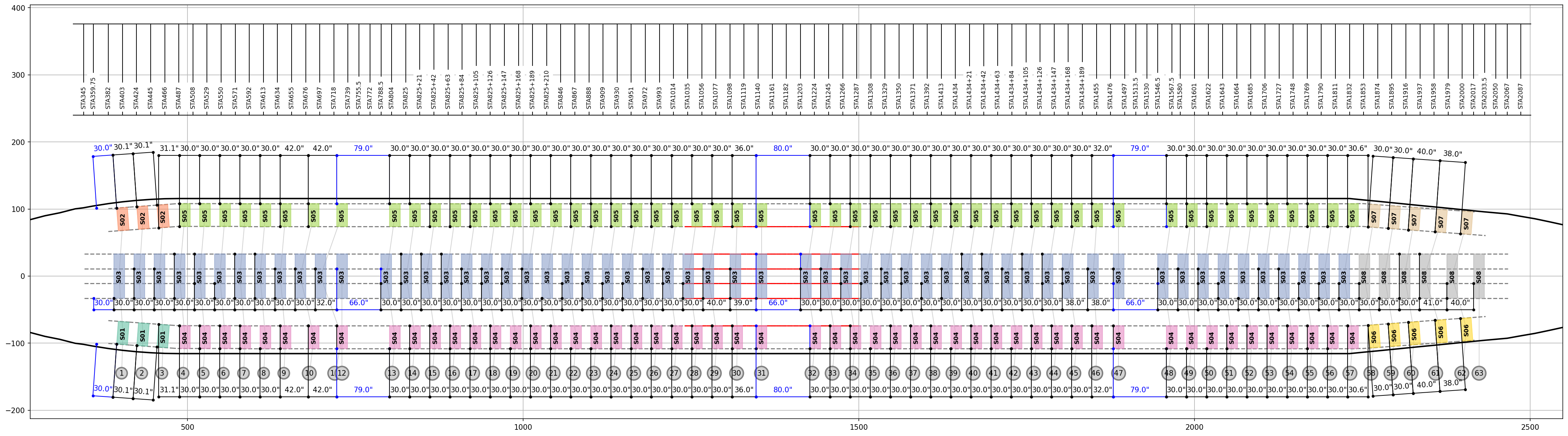
Fig. 28 Reference seating configuration, PAX ECO 2-5-2, seat pitch=30in (Third LOPA variant)
PAX-ECO-343_p32-00: standard economy class seating configuration with 2 outboard triple seats and a central quad seat installed at a pitch of 32 inches (First LOPA variant)
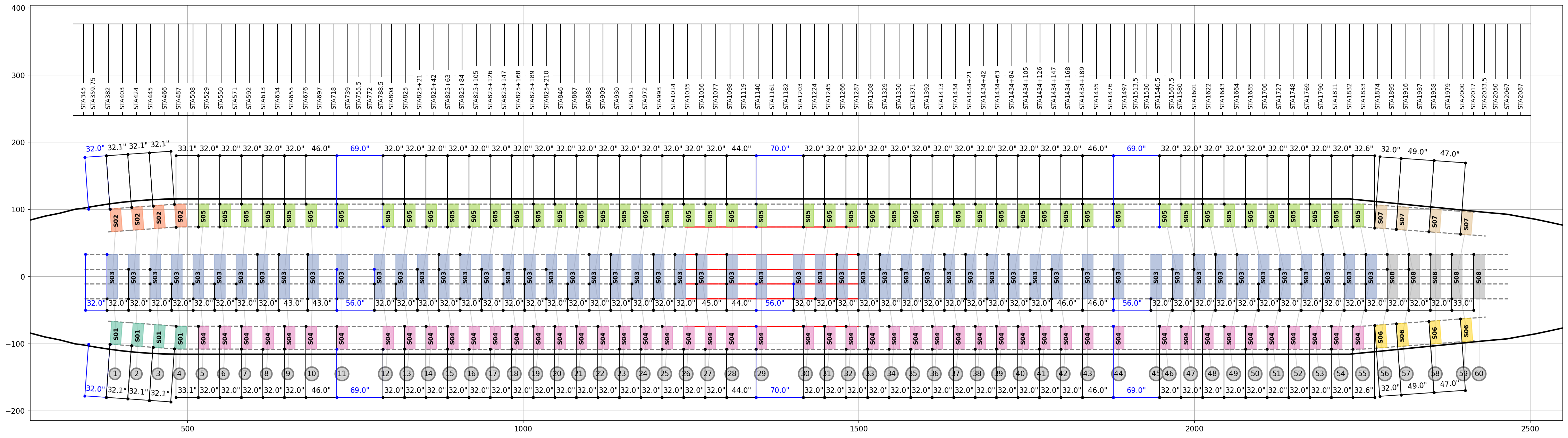
Fig. 29 Reference seating configuration, PAX ECO 3-4-3, seat pitch=32in (First LOPA variant)
The following load cases have been implemented for this seating configuration:
LCID |
Load Case Title |
QUAD Seat POC |
TRPL Seat POC |
|---|---|---|---|
1 |
TTL 9g FWD |
1111 |
111 |
2 |
TTL 9g FWD |
0111 |
110 |
3 |
TTL 9g FWD |
1110 |
011 |
4 |
TTL 9g FWD |
1010 |
101 |
5 |
TTL 6.2g DOWN |
1111 |
111 |
6 |
TTL 6.2g DOWN |
0111 |
110 |
7 |
TTL 6.2g DOWN |
1110 |
011 |
8 |
TTL 6.2g DOWN |
1010 |
101 |
9 |
TTL 4g RHS |
1111 |
111 |
10 |
TTL 4g RHS |
0111 |
110 |
11 |
TTL 4g RHS |
1110 |
011 |
12 |
TTL 4g RHS |
1010 |
101 |
PAX-ECO-343_p32-01: second LOPA variant of the Reference seating configuration PAX ECO 3-4-3. In each seating zone, front row seats have been shifted by 4in AFT.
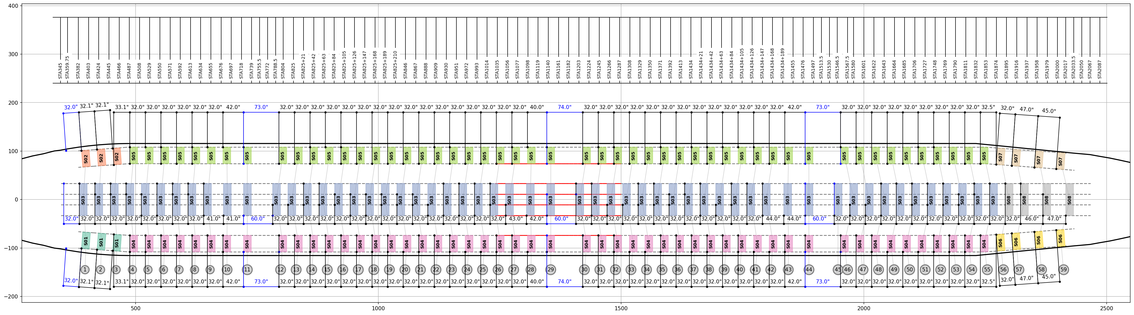
Fig. 30 Reference seating configuration, PAX ECO 3-4-3, seat pitch=32in (Second LOPA variant)
PAX-ECO-343_p32-02: third LOPA variant of the Reference seating configuration PAX ECO 3-4-3. In each seating zone, front row seats have been shifted by 8in AFT.
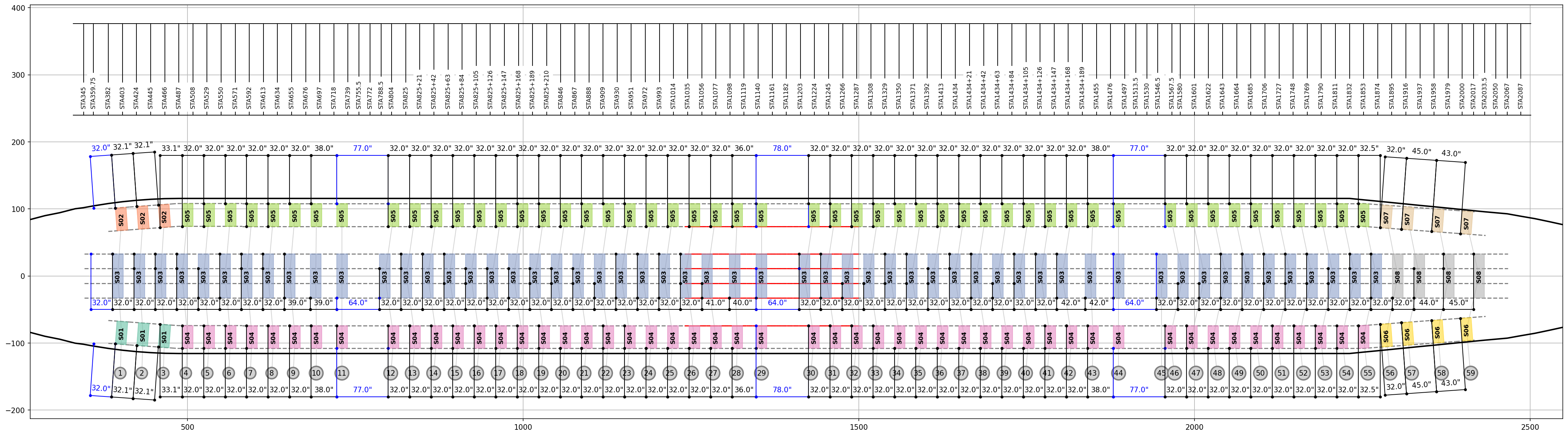
Fig. 31 Reference seating configuration, PAX ECO 3-4-3, seat pitch=32in (Third LOPA variant)
PAX-ECO-343_p32-03: fourth LOPA variant of the Reference seating configuration PAX ECO 3-4-3. In each seating zone, front row seats have been shifted by 12in AFT.

Fig. 32 Reference seating configuration, PAX ECO 3-4-3, seat pitch=32in (Third LOPA variant)
Note
Each of those seating installation have been optimised in order to maximise the interface load applied on the floor structure whilst passing all Boeing safety requirements.
Selection of installation effectivity
Based on the floor structure configuration selected at Step #1, the list of all airplanes sharing the same configuration is presented. By default all airplanes of this configuration are selected. It means that the non standard seating LOPA being justified is installed on all the airplanes listed.
Airplane listed and not affected by the installation should be deselected.
=> clicking Next triggers the analysis and the generation of a Margin of Safety table along with all deliverables (see Understanding output files).