Loading Input Data

The Loading file is an eleven sheets xlsx spreadsheet used to defined the seating installation and the floor Interface Loads.

The standard Loading file template can be downloaded under the Ressources menu of the FTools software. Two templates are available:

Although data units in one spreadsheet can be mixed, a good practice is to use a consistent set of units.

Each template is made of 11 sheets:

General guidance regarding user filled spreadsheet is presented at Filling an XLSX spreadsheet

Detailed description and filling instruction for each sheet can be found in the corresponding sheet section.

Once the Loading file is completely filled it can checked for basic mistakes with a validator

Fields Naming Conventions

Each sheet Columns (or Fields) will be presented as follows:

  • <SHEET>-<field>: Mandatory field

  • <SHEET>-<field>: Padded field

  • <SHEET>-<field>: Optional field

Where <SHEET> is the tab featuring the field, and <field> is the field name.

LOPA tabs relationships

XLSX tabs are linked together with key fields. A strong convention is that such a key is labelled as <remote-tabname>::<remote-field>. More details are provided in Understanding sheets cross references.

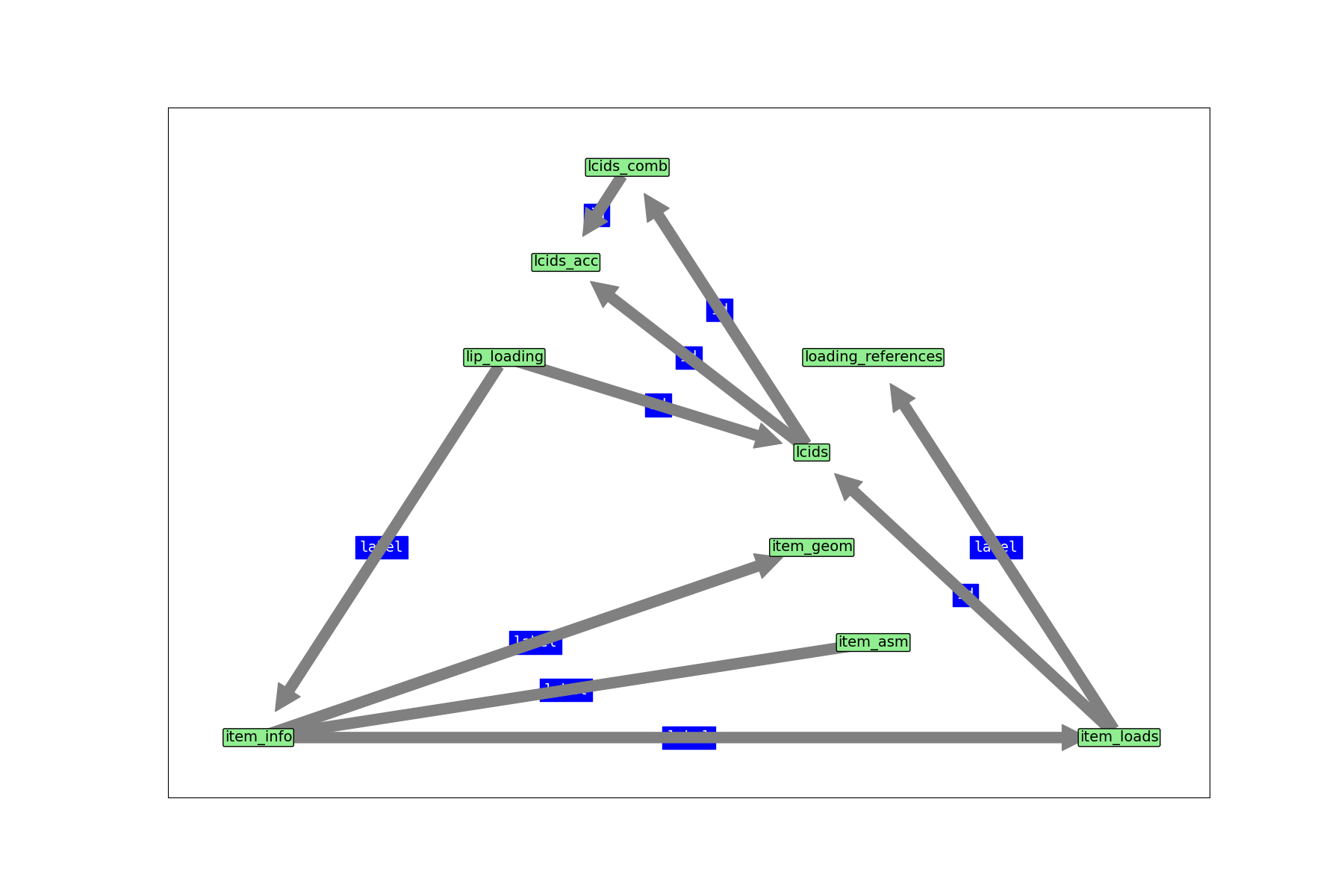
A summary of those relationships are shown Figure Fig. 33.

LOPA tabs relationships

Fig. 33 LOPA tabs relationships (click to enlarge)

Sheet “item_info

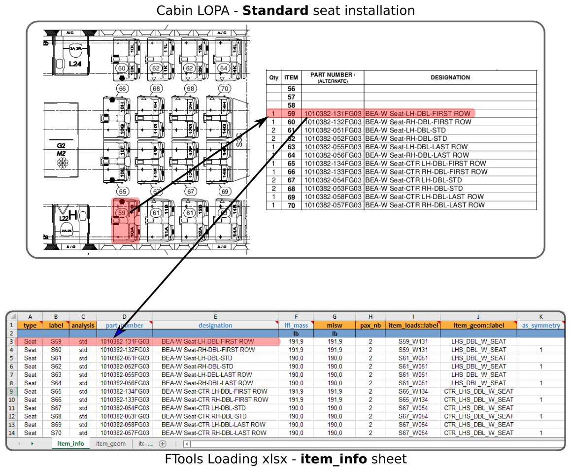
This sheet is used to define the different seats / monuments installed on the cabin LOPA. Each line corresponds to one seat or cabin monument. This sheet centralises key information and properties of each seat / cabin monument.

The following figure shows an example of standard seat definition in the sheet “item_info”:

standard seat info

Fig. 34 Example of standard seat info

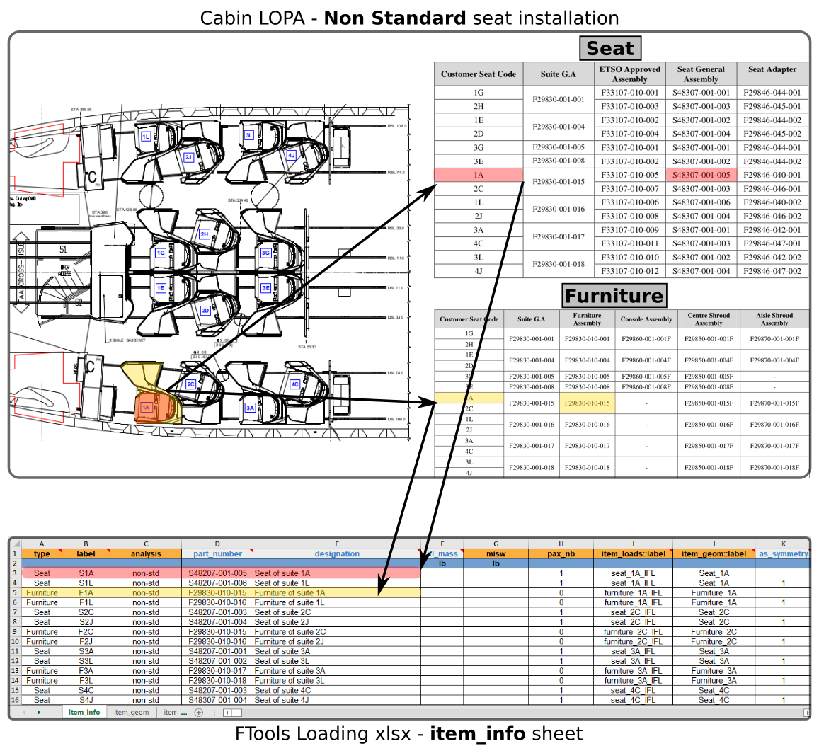
The following figure shows an example of non standard seat definition in the sheet “item_info”. In this example a seat with a surrounding furniture is captured in the “item_info” sheet.

non standard seat info

Fig. 35 Example of non standard seat info (seat + furniture)

ITEM_INFO-type

type: string | enum: ['Seat', 'Other']

Define the type of cabin item.

“Seat” should be entered in this field for standard seat installation. For any other cabin monuments defined the type “Other” should be specified.

ITEM_INFO-label

type: string

Define the cabin seat / monument label

The label specified in this field is used to refer to the cabin seat / monument. Typical label for standard seat is “Sxy” with “xy” being the seat ID shown on the cabin LOPA.

ITEM_INFO-analysis

enum: ['std', 'non-std'] | default: non-std | type: string, null

Specify the type of analysis required to justify the cabin seat / monument

For Standard seat the corresponding analysis is ‘std’ and for Non-Standard seat installation (including other cabin monuments) the corresponding analysis is ‘non-std’

ITEM_INFO-pax_nb

type: integer, null

Specify the number of passenger of the corresponding seat

This field is only mandatory for standard seat.

ITEM_INFO-part_number

type: string, null

Specify the cabin seat / monument part number

This field is complementary to the associated cabin seat / monument label.

ITEM_INFO-designation

type: string, null

Specify the cabin seat / monument designation

This field allow a complete description of the corresponding cabin seat / monument. For instance, “BEA W DBL seat RH - Last row” could be used to describe a double seat.

ITEM_INFO-iflw

dimensionality: mass | minimum: 0 | default: 0 | type: number, null

Specify the seat mass used for the interface load calculation

This field is an optional field as it is not used by the FTools in the current version. This mass will be used in a future FTools version to check the correspondance between the seat IFL and its mass.

ITEM_INFO-misw

dimensionality: mass | minimum: 0 | default: 0 | type: number, null

Specify the Maximum Installed Seat Mass

This field is a mandatory field for standard seat as it is used for the seat running load justification (seat individual weight and seat row weight). The Maximum Installed Seat Weight is the maximum allowable weight for the seat with all components and includes all equipment the seat installer may add to the seat, such as emergency equipment or literature pocket contents. This weight is equal to the minimum total tested seat weight of all static/dynamic tests used for substantiation of the subject seat P/Ns. However, this weight must be verified against seat track interface loads and other aircraft/structural limitations.

ITEM_INFO-item_loads::label

type: string

Define the IFL associated to the cabin seat / monument

This field is a cross reference to the Sheet “item_loads” and field label (see Understanding sheets cross references)

ITEM_INFO-item_geom::label

type: string

Specify the interface points associated with the cabin seat / monuments

This field is a cross reference to the Sheet “item_geom” and field “label” (see Understanding sheets cross references)

ITEM_INFO-as_symmetry

default: 0 | minimum: 0 | maximum: 1 | type: integer, null

Specify if the associated Interface Load should be made symmetric for the seat / monument

If the IFL is directly applicable to the seat / monument the field should be “0”. If the IFL should be made symmetric for the relevant seat / monument the field should be “1”.

Warning

The option as_symmetry can only be applied on seat / monument sharing the same source of IFL and the same interface point geometry. This option will symmetrize both load and geometry.

Table 1 item_info columns specifications

column

type

enum

status

default

dim

min

max

type

str

[‘Seat’, ‘Other’]

mandatory

label

str

mandatory

analysis

string, null

[‘std’, ‘non-std’]

non-std

pax_nb

integer, null

part_number

string, null

designation

string, null

iflw

number, null

0

mass

0.0

misw

number, null

0

mass

0.0

item_loads::label

str

mandatory

item_geom::label

str

mandatory

as_symmetry

integer, null

0

0.0

1.0

Note

The following column(s) need to refer to existing value(s) from other sheet(s):

Table 2 item_info columns cross-references

column

Xref sheet

Xref column

Xref check

item_loads::label

item_loads

label

isin

item_geom::label

item_geom

label

isin


Sheet “item_geom

This sheet is used to define the cabin item interface points.

The interface points can be entered in two possible ways :

  • relative: interface points are entered in a local coordinate system associated with the monument

  • absolute: interface points are entered directly in the aircraft coordinate system.

In both cases the axis of the coordinate systems are oriented in the same direction ; X pointing AFT, Y pointing starboard (RHS) and Z pointing UP.

local coordinate system

Fig. 36 Local coordinate system definition

Note

For standard seat, ‘b’ is the distance between front leg stud and aft leg pivot

Warning

Interface points must be numbered to describe a loop without intersection.

AC coordinate system

Fig. 37 Points numbering scheme

AC coordinate system

Fig. 38 AC coordinate system definition

Note

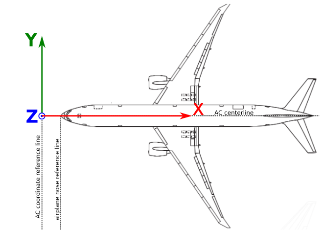
For Boeing B777 the aircraft coordinate system is defined 92.5in forward of the fuselage nose.

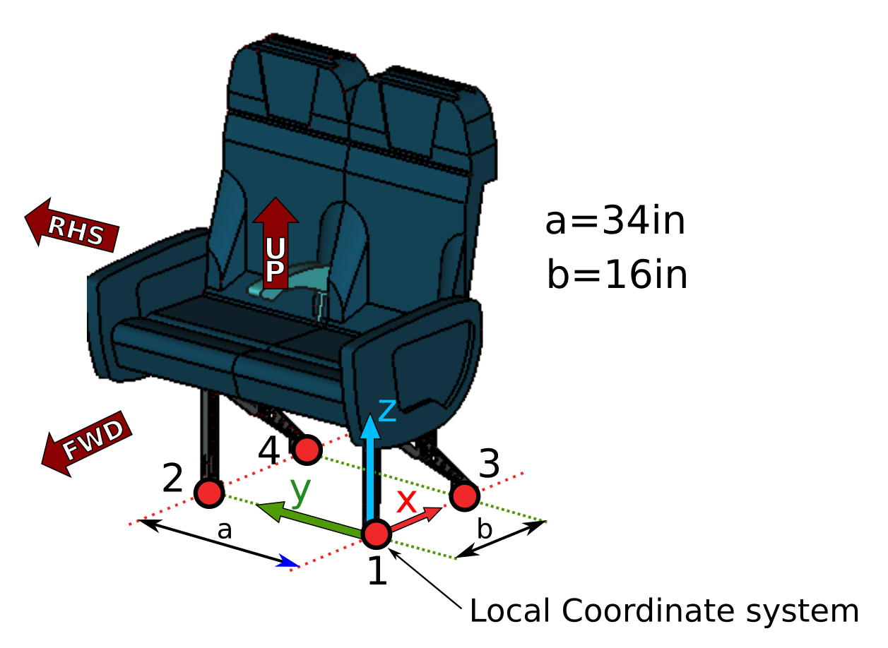
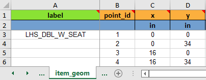
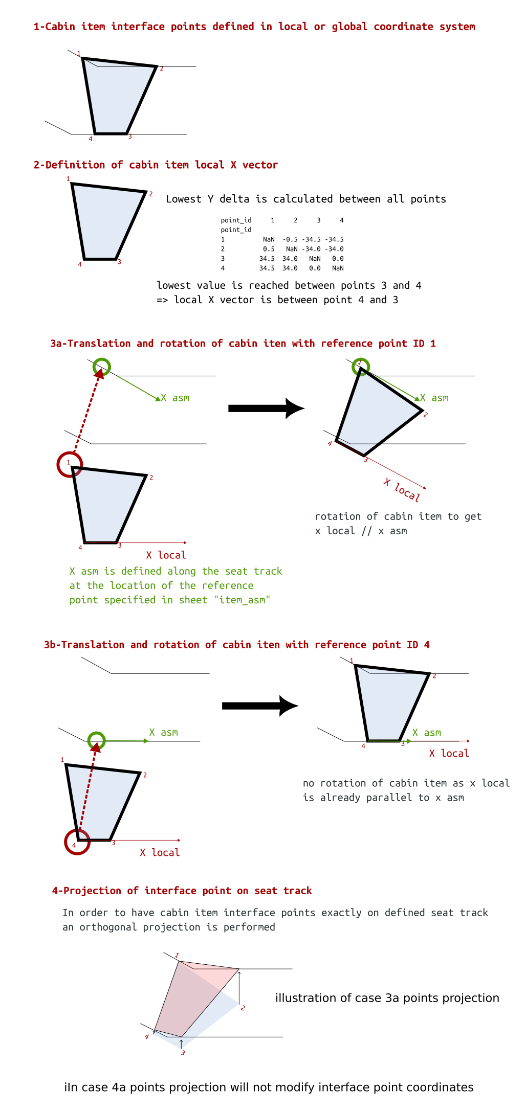
Example 1: Interface points defined in local coordinate system

The interface points of the double seat shown on Fig. 36 can be defined as shown in the following table:

Item geom defined in local coord system

Fig. 39 Interface points defined in local coordinate system

Note

‘z’ coordinate doesn’t need to be entered as it is assumed that all items are installed on seat tracks, hence ‘z’ is set to the default FE model location.

Example 2: Interface points defined in AC coordinate system

In some cases it is more convenient to define the item interface points location in the aircraft coordinate system. 
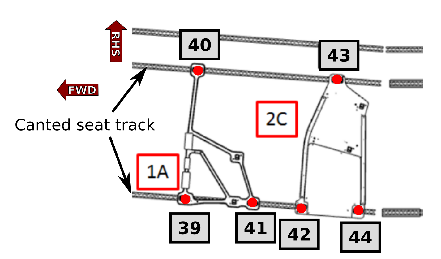
For instance in the FWD section when the Business Class seat is installed on canted seat tracks, the interface points are provided in the aicraft coordinate system.

IF points defined in AC coord system

Fig. 40 Interface points ID definition

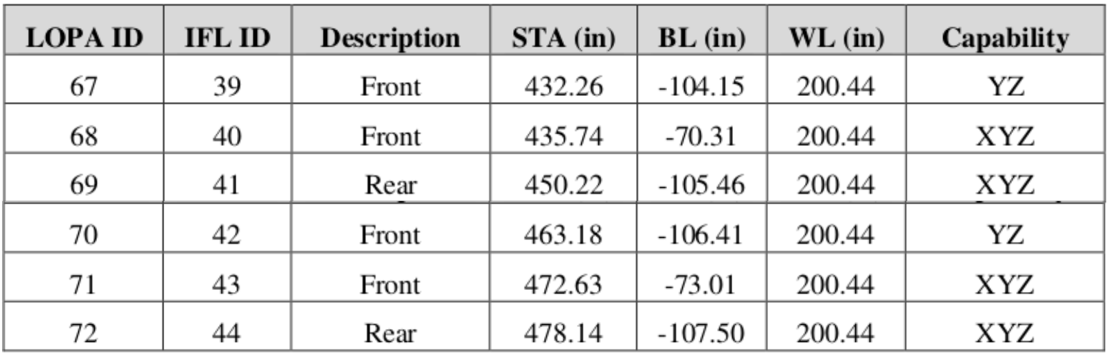
In the seat manufacturer IFL report the interface points are located in STA, BL.

Interface points in AC coord system

Fig. 41 Interface points location in AC coordinate system

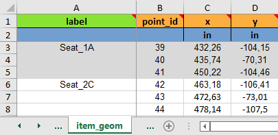
In the Sheet “item_geom”, the Seat 1A and 1C interface points can be specified as shown in the following table.

IF points defined in AC coord system

Fig. 42 Interface points defined in AC coordinate system

Warning

Interface point X coordinate specified in global coordinate should not be mixed with aircraft station STA. 
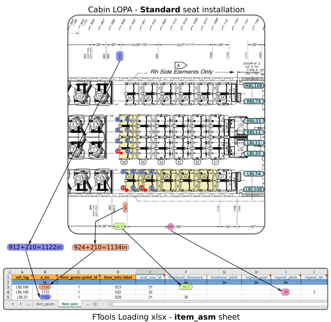
For instance, an interface point located at STA909 on a Boeing B777-300 should be converted to X=909+210=1’119in

Tip

Interface points location can be entered in local or global coordinate system as long as it remains consistent per item. A good practice is to used the same interface point ID as the one defined in the IFL report. It will ease the Interface Load entering in Sheet “item_loads”

Note

The interface points ID entered in this sheet correspond to the IFL ID and not the LOPA ID from the seat manufacturer report. The same point ID will be used in the Sheet “item_loads”” to specify the interface load.

ITEM_GEOM-label

pattern: ^[a-zA-Z_][\w]*$ | default: _pad_ | type: string, null

Define the label of the cabin item interface points

This label is used in Sheet “item_loads” and Sheet “item_asm” to refer to the interface points.

The ‘label’ should be entered as a text format with no space. For instance, the following ‘label’ can be specified ‘seat_PN142’.

ITEM_GEOM-point_id

type: integer

Specify the ID of the item interface point

This ID should be a unique integer for a given ‘item_label’. In other words, the ‘point_id’ should be unique per item.

ITEM_GEOM-x

type: number | dimensionality: length

Enter X location of cabin item interface point in local or global coordinate system

ITEM_GEOM-y

type: number | dimensionality: length

Enter Y location of cabin item interface point in local or global coordinate system

Table 3 item_geom columns specifications

column

default

type

status

dim

set

label

_pad_

string, null

padded

Set (a)

point_id

int

mandatory

Set (a)

x

float

mandatory

length

y

float

mandatory

length

Note

The following set(s) of columns combination need to be unique:

  • Set (a): label, point_id


Sheet “item_asm

The sheet is used to define the installation of cabin item as specified on the LOPA.

The item installation is restricted to seat tracks.

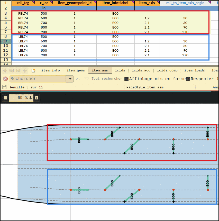
Fig. 43 illustrates the data filling of sheet “item_asm” for a standard seat installation.

Example of standard seat installation specification

Fig. 43 Example of Item assembly specification for standard seat installation

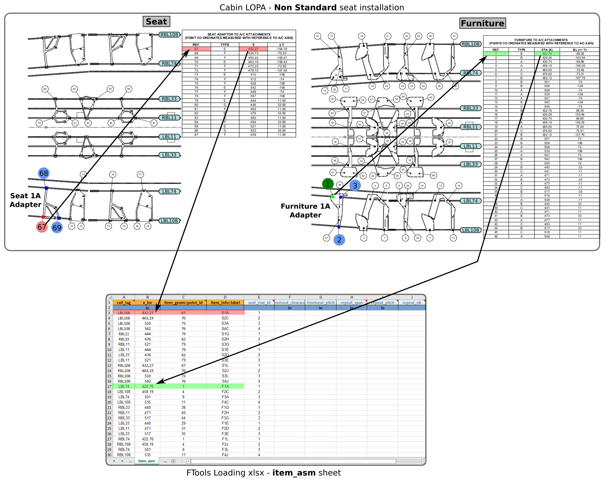
Fig. 44 illustrates the data filling of sheet “item_asm” for a non standard seat installation (Business class seat with surrounding furniture).

Example of non standard seat installation specification

Fig. 44 Example of Item assembly specification for non standard seat installation

Note

In the example of Fig. 44, Seat 1A and Furniture 1A reference points are located on FWD canted seat track (BL-104.16 and BL-69.38 respectively). However, in sheet “item_asm”, rail_tag is entered as LBL108 and LBL74. Internally, FTools performs an automatic positioning with rail_tag and x_loc definition.

Warning

when the seat / cabin item is installed with some interface points on both canted and straight seat track, selection of the “reference point” is very important as it can lead to different location. (see Fig. 45)

Understanding installation in transition area

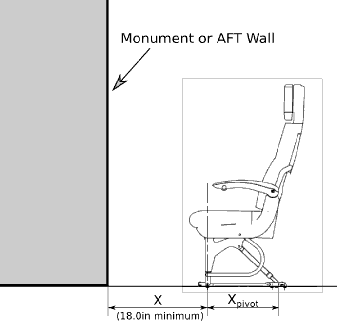
The following figure illustrates the seat / cabin assembly process in FWD transition area. As shown on Fig. 45 the selection of different reference point leads to two different cabin item installation.

assembly process

Fig. 45 Assembly of cabin item in transition area

This capability to select the orientation of the installed item (along canted part of seat track or along straight seat track) is usefull in some peculiar cases. For instance in this transition zone, a seat can be installed along the line of flight or along the canted seat track.

ITEM_ASM-rail_tag

type: string | pattern: ^[L|l|r|R][B|b][L|l]\d+((\.|,)\d+)?$

Define seat track by ‘rail_tag’ where the item reference point is located

The list of available ‘rail_tag’ depends on the aircraft type and floor structure configuration “fsconf”.

Note

On standard B777 the following ‘rail_tag’ are available: ‘LBL108’, ‘LBL74’, ‘LBL33’, ‘LBL11’, ‘RBL11’, ‘RBL33’, ‘RBL74’ and ‘RBL108’

ITEM_ASM-x_loc

type: number | dimensionality: length

Specify the X location of the cabin item (seat or other monument) reference point

Warning

The ‘x_loc’ is defined in the AC coordinate system and it shouldn’t be mixed with aircraft station (see example of Fig. 43 for STA to x_loc conversion)

ITEM_ASM-item_geom::point_id

type: integer

Specify the ID of the item interface point

This ID is a cross reference to a point ID specified in Sheet “item_geom”

(see Understanding sheets cross references)

Note

Any ‘point_id’ of the item interface points can be used as reference point.

ITEM_ASM-item_info::label

type: string | pattern: ^[a-zA-Z_][\w]*$

Define the label of the cabin item

This label is a cross reference to a label specified in Sheet “item_info”

(see Understanding sheets cross references)

ITEM_ASM-item_axis

pattern: ^\s*\d+\s*,\s*\d+\s*$ | type: string, null

The item_axis field is used simutaneously with rail_to_item_axis_angle field.

ITEM_ASM-rail_to_item_axis_angle

minimum: 0 | maximum: 360 | type: number, null

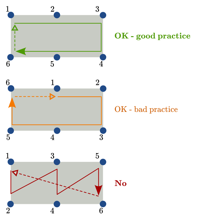
The rail_to_item_axis_angle field is used simutaneously with item_axis field.

When item_axis is provided, the placement of the relevant item will be rotated around the item reference point by the angle specified in this field. The angle is provided in degrees.

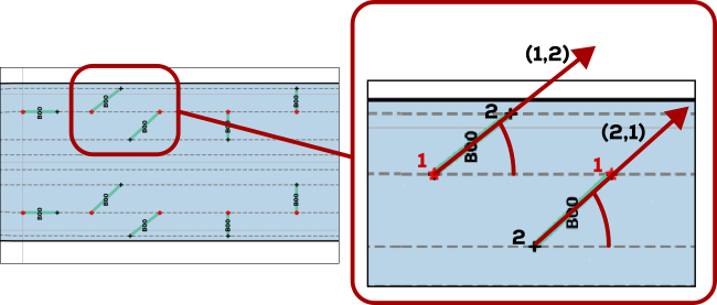
The following figure shows an example of the same bulkhead with different orientations.

The angle is defined as the the angle between the rail X axis (+X axis in a regular section) and the two points vector described in item_axis. In Fig. 47 the bulkhead located at X=600in and X=700in have the same reference point and same specified angle. The difference is the item_axis specification. For the one located at X=600, the vector goes from poit 1 to point 2, whereas this is reversed for the latter, hence the difference in the placement. A detailed picture is shown in Fig. 46.

Rail to Item Axis angle specifications

Fig. 46 Rail to Item Axis angle specifications

Rail to Item Axis angle example

Fig. 47 Rail to Item Axis angle example

ITEM_ASM-frontseat_clearance

dimensionality: length | minimum: 0 | type: number, null

Specify the clearance between a monument and a front row seat (fwd stud)

This value ‘X’ is used to calculate the equivalent seat pitch for front row seat based on the Boeing D6-36238 formula:

\[pitch=(X-4)+X_{pivot}\]
front seat clearance

Fig. 48 Front seat clearance definition

ITEM_ASM-frontseat_pitch

dimensionality: length | minimum: 0 | type: number, null

Specify the pitch associated with a front row seat

This value overides the default seat pitch automatically calculated.

ITEM_ASM-seat_row_id

minimum: 0 | default: 0 | type: integer, null

Specify the row ID of the corresponding seat

ITEM_ASM-repeat_span

dimensionality: length | minimum: 1 | type: number, null

Specify the span used for the definition of item repetitions installation

This field should be used in combination with field “repeat_pitch” or “repeat_nb” to specify multiple installation of one cabin item (seat or monument).

(see Fig. 49 for repeat parameters definition and Fig. 50 for example)

ITEM_ASM-repeat_pitch

dimensionality: length | minimum: 1 | type: number, null

Specify the pitch used for the repetition of the item installation

This field “repeat_pitch” can be used with the field “repeat_nb” or “repeat_span” to specify multiple installation of one cabin item (seat or monument).

(see Fig. 49 for repeat parameters definition and Fig. 50 for example)

ITEM_ASM-repeat_nb

minimum: 1 | type: integer, null

Specify the number of repetitions used for the item installation

This field should be used in combination of a specified “pitch” or a “span”

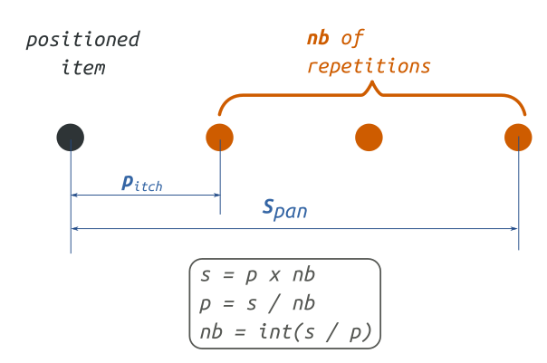
Theoretical explanation of repeat function in FTools

Fig. 49 presents a schematic view of how the FTools repeat function is built with the three parameters (repeat_pitch, repeat_nb and repeat_span). A combination of two of the three parameters is enough to define an item repetition.

Repeat assembly explanation

Fig. 49 Illustration of the three repeat parameters.

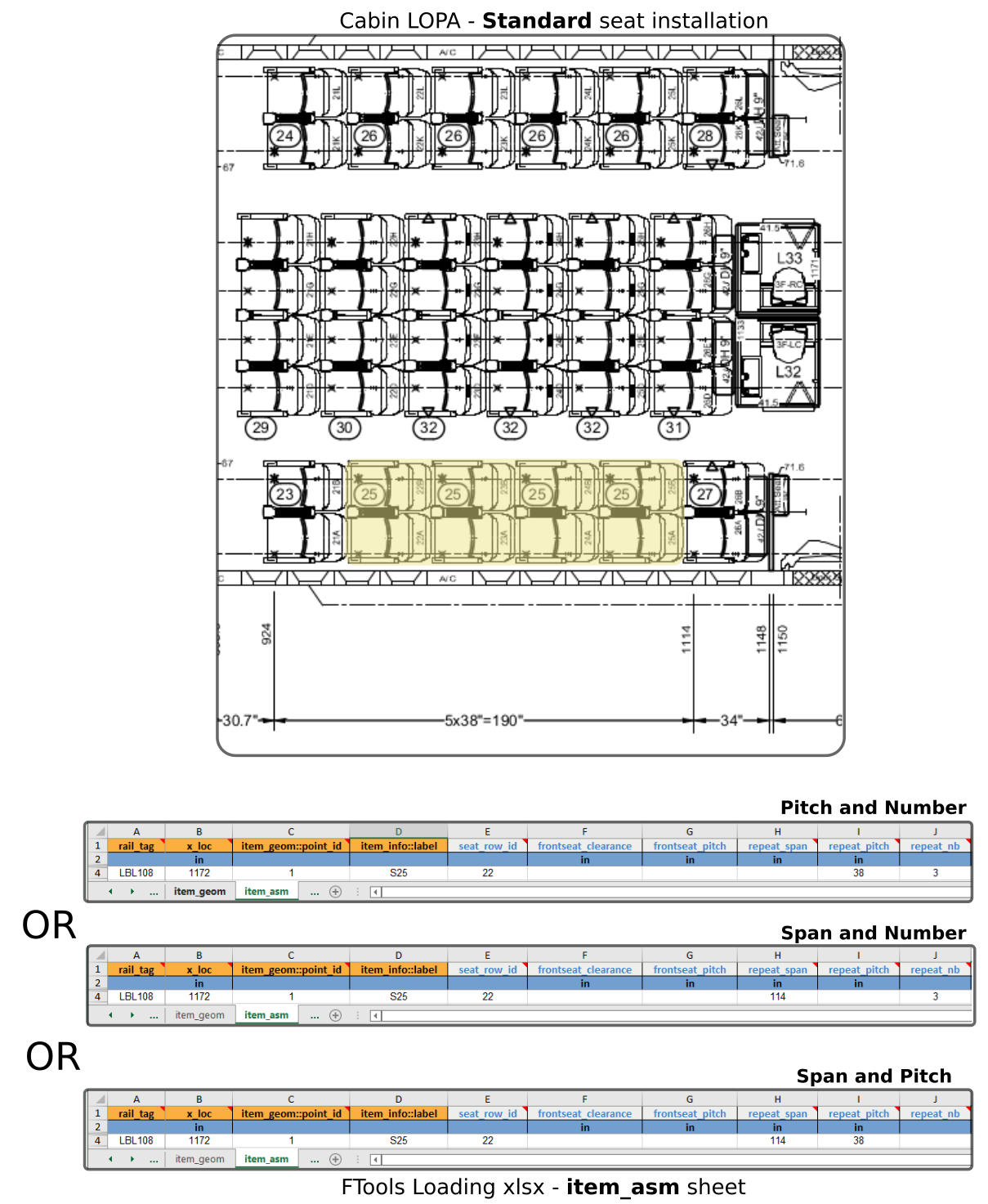
Example of item installation repetition definition

Fig. 50 illustrates three possible ways of entering the installation of four seats S25 on the outboard left side.

Repeat assembly example

Fig. 50 Example of same seat repetition written in three different ways

Table 4 item_asm columns specifications

column

type

status

dim

min

max

default

set

rail_tag

str

mandatory

Set (a)

x_loc

float

mandatory

length

Set (a)

item_geom::point_id

int

mandatory

item_info::label

str

mandatory

item_axis

string, null

rail_to_item_axis_angle

number, null

0.0

360.0

frontseat_clearance

number, null

length

0.0

frontseat_pitch

number, null

length

0.0

seat_row_id

integer, null

0.0

0.0

repeat_span

number, null

length

1.0

repeat_pitch

number, null

length

1.0

repeat_nb

integer, null

1.0

Note

The following set(s) of columns combination need to be unique:

  • Set (a): rail_tag, x_loc

Note

The following column(s) need to refer to existing value(s) from other sheet(s):

Table 5 item_asm columns cross-references

column

Xref sheet

Xref column

Xref check

item_info::label

item_info

label

isin


Sheet “lcids

This sheet is used to define the installation load cases corresponding to the IFL specified in Sheet “item_loads”

It creates an association between load case ID and its label. This sheet can be also used to define combined load cases.

Fig. 51 and Fig. 52 illustrates two possible load cases definition.

lcids example 01

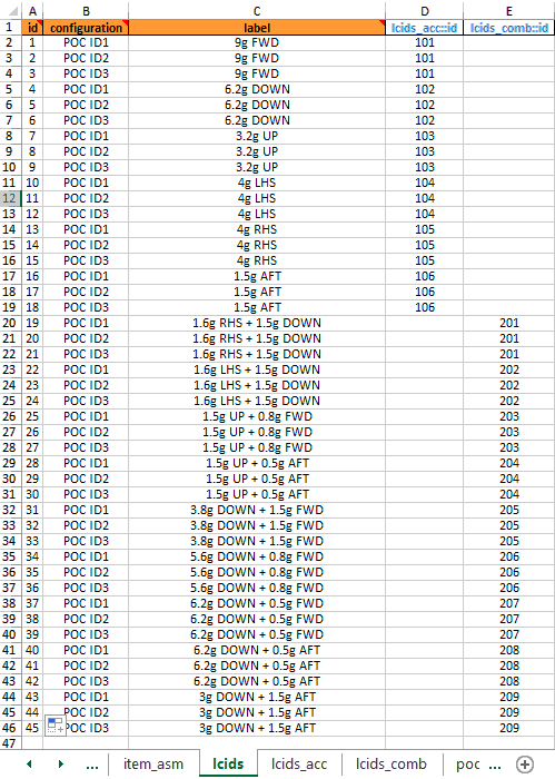
Fig. 51 Example of load cases definition (Standard seats with different POC)

lcids example 02

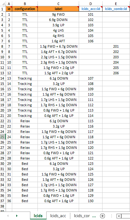
Fig. 52 Example of load cases definition (Business class seats with different positioning)

Note

In the example of Fig. 52 combined load cases are entered in two different ways. For load case ID 7 to 12, the FTools linear load case combination is used, whereas for load case ID 15 to 20, 23 to 28, 31 to 36 the interface loads are directly provided in Sheet “item_loads”

LCIDS-id

type: integer

Define the load case ID and should be a unique integer.

This ID is used by the FTools to refere to a single load case. This ID is associated to a set of Interface load defined in Sheet “item_loads”

LCIDS-configuration

type: string

Specify the load case configuration

Standard seat

For standard seats, Interface Loads are provided with all seats in Taxi, Take Off and Landing (TTOL) position but with different Passenger Occupancy Combination (POC). Those different seating combination can be specified through this configuration field. For instance, a 9g FWD load case can be associated with a “full occupancy” or “partial occupancy” configuration. In Fig. 51, configuration “POC ID1” corresponds to all seats fully occupied; configuration “POC ID2” corresponds to all seats partially occupied outboad and configuration “POC ID3” corresponds to all seats partially occupied inboard.

Non standard seat

Non standard seat, like Business class seat, can have Interface Load generated at different seat position: “TTOL, Tracking, Relax, Bed, etc…”. Those positions are recorded in this configuration field.

Standard and non standard seat

For a cabin LOPA mixing standard and non standard seat, the configuration field should be used to describe the associated configuration of all seats. For instance it can be “TTOL - Fully occupied”.

LCIDS-label

type: string

Specify the load case label in a text format.

For instance a typical ‘label’ can be ‘9g FWD’.

LCIDS-lcids_acc::id

type: integer, null

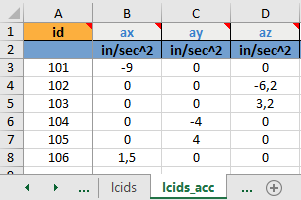
Specify the ID of a corresponding acceleration

This field is a cross reference to an ID of an acceleration defined in Sheet “lcids_acc”

(see also Understanding sheets cross references)

LCIDS-lcids_comb::id

type: integer, null

Specify the ID of a corresponding linear load case combination

This field is a cross reference to an ID of a combined load case combination defined in Sheet “lcids_comb”

(see also Understanding sheets cross references)

Table 6 lcids columns specifications

column

type

status

set

id

int

mandatory

configuration

str

mandatory

Set (config_label)

label

str

mandatory

Set (config_label)

lcids_acc::id

integer, null

lcids_comb::id

integer, null

Note

The following set(s) of columns combination need to be unique:

  • Set (config_label): configuration, label

Note

The following column(s) need to refer to existing value(s) from other sheet(s):

Table 7 lcids columns cross-references

column

Xref sheet

Xref column

Xref check

lcids_acc::id

lcids_acc

id

isin

lcids_comb::id

lcids_comb

id

isin


Sheet “lcids_acc

Specify the acceleration factor in aircraft axis

Refer to Fig. 38 for aicraft coordinate system definition.

In the example of Fig. 53 the following acceleration factors are defined:

  • “101: ax=-9 in/s²”

  • “102: az=-6.2 in/s²”

  • “103: az=3.2 in/s²”

  • “104: ay=-4 in/s²”

  • “105: ay=4 in/s²”

  • “106: ax=1.5 in/s²”

Load case acceleration factor

Fig. 53 Load case acceleration factor definition

LCIDS_ACC-id

type: integer

Define the ID of the acceleration factor set

This ID is used in the load case definition (Sheet “lcids”) and in the load case combination (Sheet “lcids_comb”)

LCIDS_ACC-ax

default: 0.0 | type: number, null

Specify the acceleration factor in the X-axis

Refer to Fig. 38 for aicraft coordinate system definition.

LCIDS_ACC-ay

default: 0.0 | type: number, null

Specify the acceleration factor in the Y-axis

Refer to Fig. 38 for aicraft coordinate system definition.

LCIDS_ACC-az

default: 0.0 | type: number, null

Specify the acceleration factor in the Z-axis

Refer to Fig. 38 for aicraft coordinate system definition.

Table 8 lcids_acc columns specifications

column

type

status

default

id

int

mandatory

ax

number, null

0.0

ay

number, null

0.0

az

number, null

0.0


Sheet “lcids_comb

Define a load case linear combination

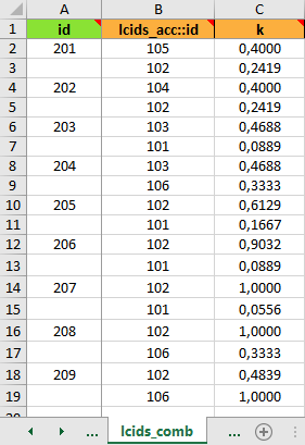
When the cabin item (seat or monument) Interface Load (IFL) is generated by a linear combination of two elementary load cases it is possible to use the FTools load case combination facility in order to define this load case. It prevents an additional Interface Load definition in Sheet “item_loads”.

Fig. 54 provides an example of load case linear combination definition. For instance, ID 201 defines a linear combination of load case ID 105 and ID 102 with a combination factor k=0.4=1.6/4 and k=0.2419=1.5/6.2 respectively. In this example, load case acceleration factors are those specified in Fig. 53.

ID 201 = (1.6/4) x 4 ay + (1.5/6.2) x -6.2 az = 1.6 ay -1.5 az = 1.6g RHS + 1.5g DOWN

Load case combination

Fig. 54 Load case combination definition

LCIDS_COMB-id

default: _pad_ | type: integer, null

Define the IF of a linear load case combination

This ID is used in Sheet “lcids” for the load case definition

LCIDS_COMB-lcids_acc::id

type: integer

Specify the ID of an elementary load acceleration factor

This field is a cross reference to an ID of an acceleration factor defined in Sheet “lcids_acc”

LCIDS_COMB-k

type: number

Specify the coefficient to apply to the elementary load acceleration factor

Table 9 lcids_comb columns specifications

column

default

type

status

set

id

_pad_

integer, null

padded

Set (comb)

lcids_acc::id

int

mandatory

Set (comb)

k

float

mandatory

Note

The following set(s) of columns combination need to be unique:

  • Set (comb): id, lcids_acc::id

Note

The following column(s) need to refer to existing value(s) from other sheet(s):

Table 10 lcids_comb columns cross-references

column

Xref sheet

Xref column

Xref check

lcids_acc::id

lcids_acc

id

isin


Sheet “item_loads

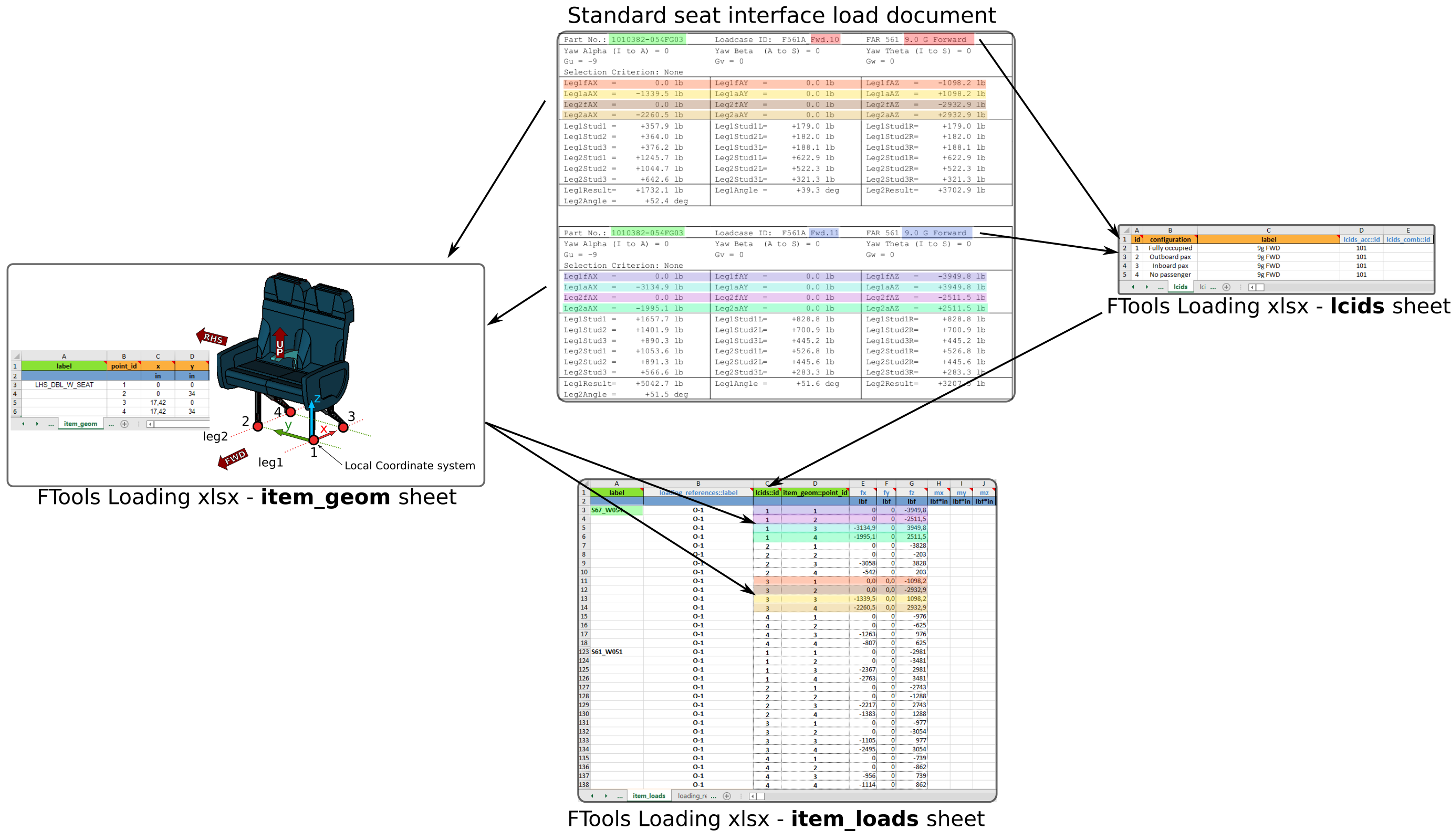
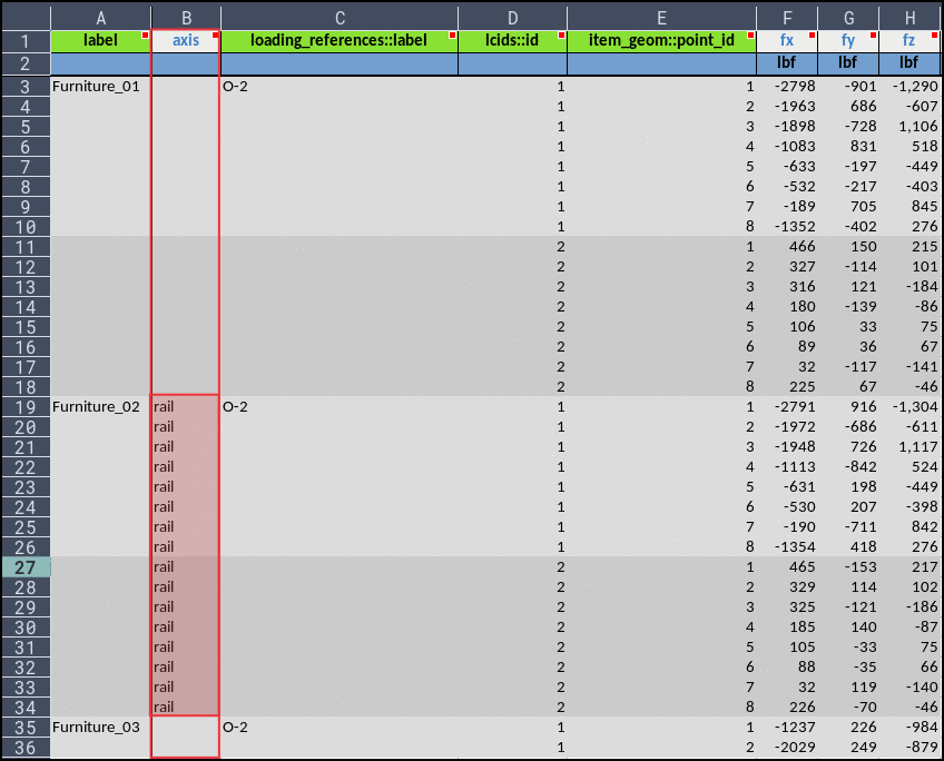
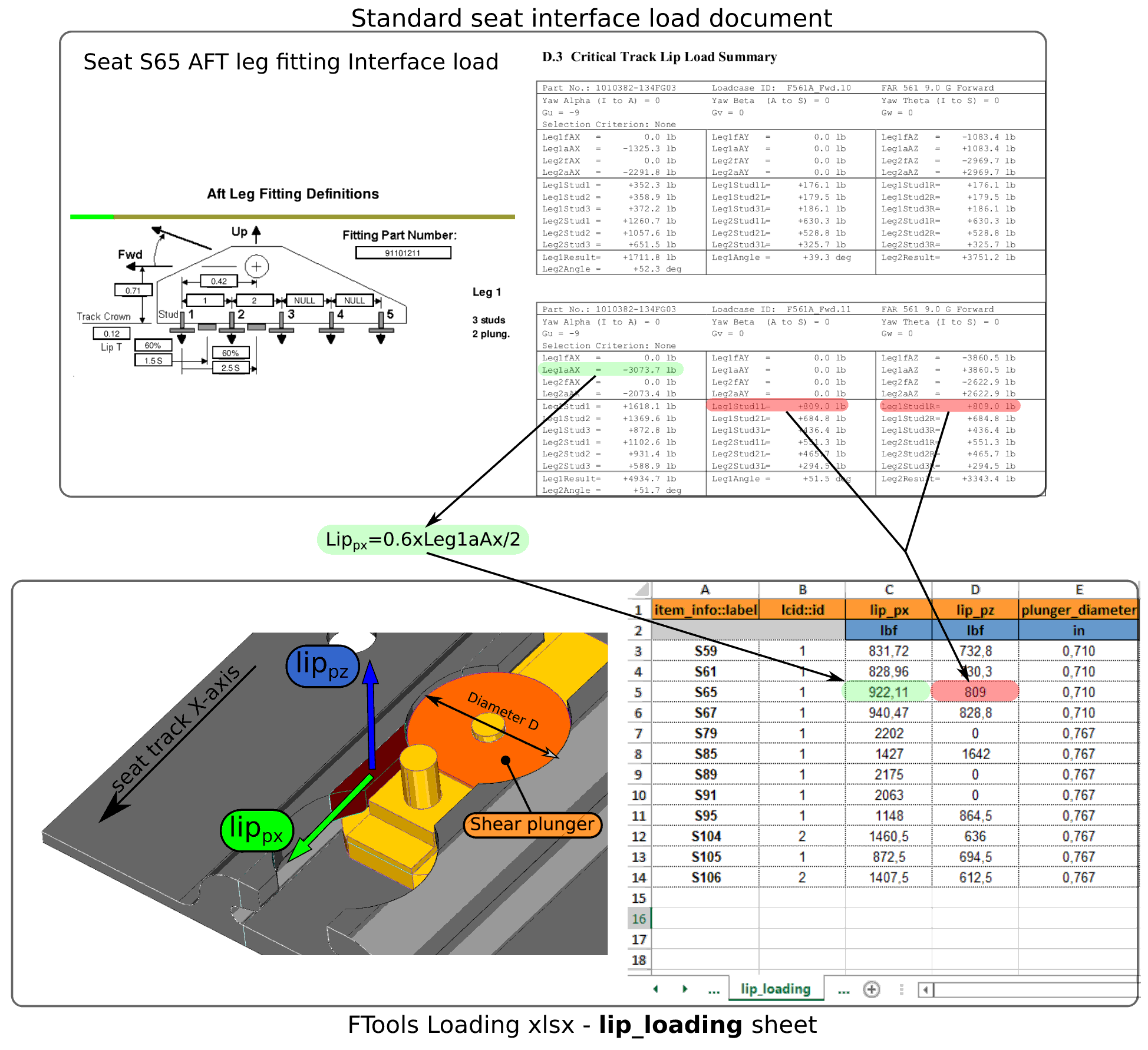
The sheet is made to specify the loading applied on interface points. The interface load entered in this sheet are loading applied on the floor structure by the cabin.

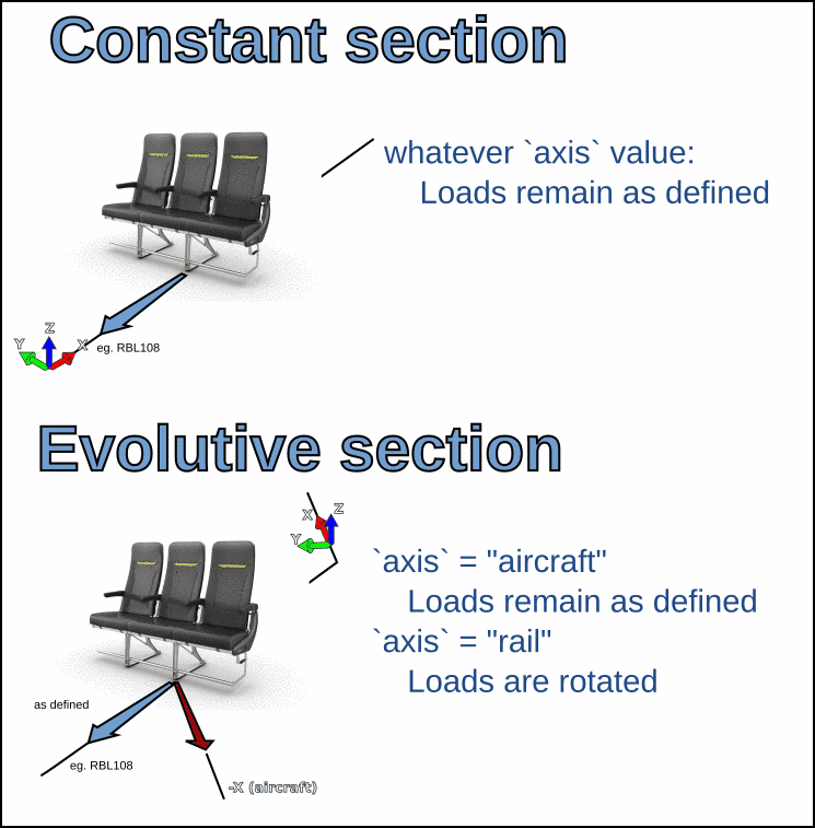
IFL are defined in aircraft coordinate system by default. This may be adjusted by using axis field.

Warning

In canted section, interface load provided in seat track coordinate system must either:

  • be converted to aircraft coordinate system for entry in this sheet.

  • activate axis field

Example of loading definition

Fig. 55 illustrates the interface load definition for two seats S67 and S61. Both seats have four interface points with their ID going from 1 to 4.

Item loads example

Fig. 55 Example of interface load definition

ITEM_LOADS-label

pattern: ^.*$ | default: _pad_ | type: string, null

Specify the label of the cabin item IFL

This label will be used to link a set of Interface Loads to a cabin item (seat / monument). This link is defined in the Sheet “item_info”.

ITEM_LOADS-axis

default: aircraft | enum: ['rail', 'aircraft'] | type: string, null

IFL are by default assumed to be submitted in AC Coordinates System. This is the case if axis is let blank, or filled with aircraft value.

If rail is entered, loads will be assumed to be described in Rail axis System.

Warning

To ensure backward compatibility with V2 input file, data are not tabbed, therefore, the whole block must be filled, as shown Fig. 56.

Example of item_loads::axis use

Fig. 56 Example of item_loads::axis use

The use of item_loads::axis has no impact on regular sections, since AC global axis and rail local axis are aligned.

item_loads::axis definition

Fig. 57 item_loads::axis definition

ITEM_LOADS-loading_references::label

default: _pad_ | type: string, null

Specify the label of the loading reference of the IFL entered in the line

This field is a cross reference to a label defined in Sheet “loading_references”

(see also Understanding sheets cross references)

ITEM_LOADS-lcids::id

default: _pad_ | type: integer, null

Specify an ID of a load case defined in Sheet “lcids” and corresponding to the IFL entered in the line

ITEM_LOADS-item_geom::point_id

type: integer | default: _pad_

Specify the ID of the interface points defined in the Sheet “item_geom”

Normally all the interface points of an item should be listed once for a given load case. If one interface point is omitted no loading will be considered applied on it.

This field is a cross reference to the field ‘point_id’ of the Sheet “item_geom”.

(see also Understanding sheets cross references)

ITEM_LOADS-fx

dimensionality: force | default: 0.0 | type: number, null

Enter loading force applied to the floor structure in X direction

See Fig. 38 for the definition of aircraft coordinate system used for force orientation.

ITEM_LOADS-fy

dimensionality: force | default: 0.0 | type: number, null

Enter loading force applied to the floor structure in Y direction

See Fig. 38 for the definition of aircraft coordinate system used for force orientation.

ITEM_LOADS-fz

dimensionality: force | default: 0.0 | type: number, null

Enter loading force applied to the floor structure in Z direction

See Fig. 38 for the definition of aircraft coordinate system used for force orientation.

ITEM_LOADS-mx

dimensionality: moment | default: 0.0 | type: number, null

Enter loading moment applied to the floor structure around X axis

See Fig. 38 for the definition of aircraft coordinate system used for moment orientation.

ITEM_LOADS-my

dimensionality: moment | default: 0.0 | type: number, null

Enter loading moment applied to the floor structure around Y axis

See Fig. 38 for the definition of aircraft coordinate system used for moment orientation.

ITEM_LOADS-mz

dimensionality: moment | default: 0.0 | type: number, null

Enter loading moment applied to the floor structure around Z axis

See Fig. 38 for the definition of aircraft coordinate system used for moment orientation.

Table 11 item_loads columns specifications

column

default

type

status

enum

dim

set

label

_pad_

string, null

padded

Set (a)

axis

aircraft

string, null

[‘rail’, ‘aircraft’]

loading_references::label

_pad_

string, null

padded

lcids::id

_pad_

integer, null

padded

Set (a)

item_geom::point_id

_pad_

int

padded

Set (a)

fx

0.0

number, null

force

fy

0.0

number, null

force

fz

0.0

number, null

force

mx

0.0

number, null

moment

my

0.0

number, null

moment

mz

0.0

number, null

moment

Note

The following set(s) of columns combination need to be unique:

  • Set (a): label, lcids::id, item_geom::point_id

Note

The following column(s) need to refer to existing value(s) from other sheet(s):

Table 12 item_loads columns cross-references

column

Xref sheet

Xref column

Xref check

loading_references::label

loading_references

label

isin

lcids::id

lcids

id

isin


Sheet “loading_references

This sheet is used to provide document reference regarding the IFL entered in the Sheet “item_loads”

Reference document with revision should be used to ensure a correct traceability of Interface Load. The list of document(s) entered in this sheet will be presented in the Structural Substantiation Report (SSR).

Here is an example of IFL reference document definition:

loading reference document

Fig. 58 IFL reference document definition

LOADING_REFERENCES-label

type: string

Enter label to make cross link to reference document

The label entered here should be a short keyword to create a cross reference between the document full description and the IFL entered in the Sheet “item_loads”.

For more information on sheets cross reference please refer to Filling an XLSX spreadsheet

LOADING_REFERENCES-document

type: string

Enter IFL reference document identification number.

LOADING_REFERENCES-revision

type: string

Enter IFL reference document revision

Revision is entered in a text format (‘string’), therefore revision written like A, B, C,… and 01, 02, 03,.. are both possible

LOADING_REFERENCES-title

type: string

Enter IFL reference document title

Table 13 loading_references columns specifications

column

type

status

set

label

str

mandatory

Set (a)

document

str

mandatory

Set (a)

revision

str

mandatory

Set (a)

title

str

mandatory

Set (a)

Note

The following set(s) of columns combination need to be unique:

  • Set (a): label, document, revision, title


Sheet “lip_loading

This sheet is used to specify the critical seat track lip loading

Lip loading specified in the sheet is used by the FTools for the substantiation of the seat track lip under critical tension and shear.

lip load example

Fig. 59 Example of seat track lip loading definition

LIP_LOADING-item_info::label

type: string

Specify the cabin item (seat or monument) associated with the critical lip loading defined

The label entered here is cross reference to the field ‘label’ of the Sheet “item_info”

(see also Understanding sheets cross references)

LIP_LOADING-lcid::id

type: integer, null

Specify the ID of the load case providing the critical lip loading defined

The ID entered here is cross reference to the field ‘ID’ of the Sheet “lcids”

(see also Understanding sheets cross references)

LIP_LOADING-lip_px

type: number | dimensionality: force

Define the horizontal shear force applied on one seat track lip

(see Fig. 59 for load definition)

LIP_LOADING-lip_pz

type: number | dimensionality: force

Define the vertical force applied on one seat track lip

(see Fig. 59 for load definition)

LIP_LOADING-plunger_diameter

type: number | dimensionality: length

Define the shear plunger diameter used to apply horizontal shear load on seat track lips

(see Fig. 59 for shear plunger diameter definition)

Table 14 lip_loading columns specifications

column

type

status

dim

set

item_info::label

str

mandatory

Set (loading)

lcid::id

integer, null

Set (loading)

lip_px

float

mandatory

force

lip_pz

float

mandatory

force

plunger_diameter

float

mandatory

length

Note

The following set(s) of columns combination need to be unique:

  • Set (loading): item_info::label, lcid::id

Note

The following column(s) need to refer to existing value(s) from other sheet(s):

Table 15 lip_loading columns cross-references

column

Xref sheet

Xref column

Xref check

item_info::label

item_info

label

isin

lcid::id

lcids

id

isin


Sheet “std_alw

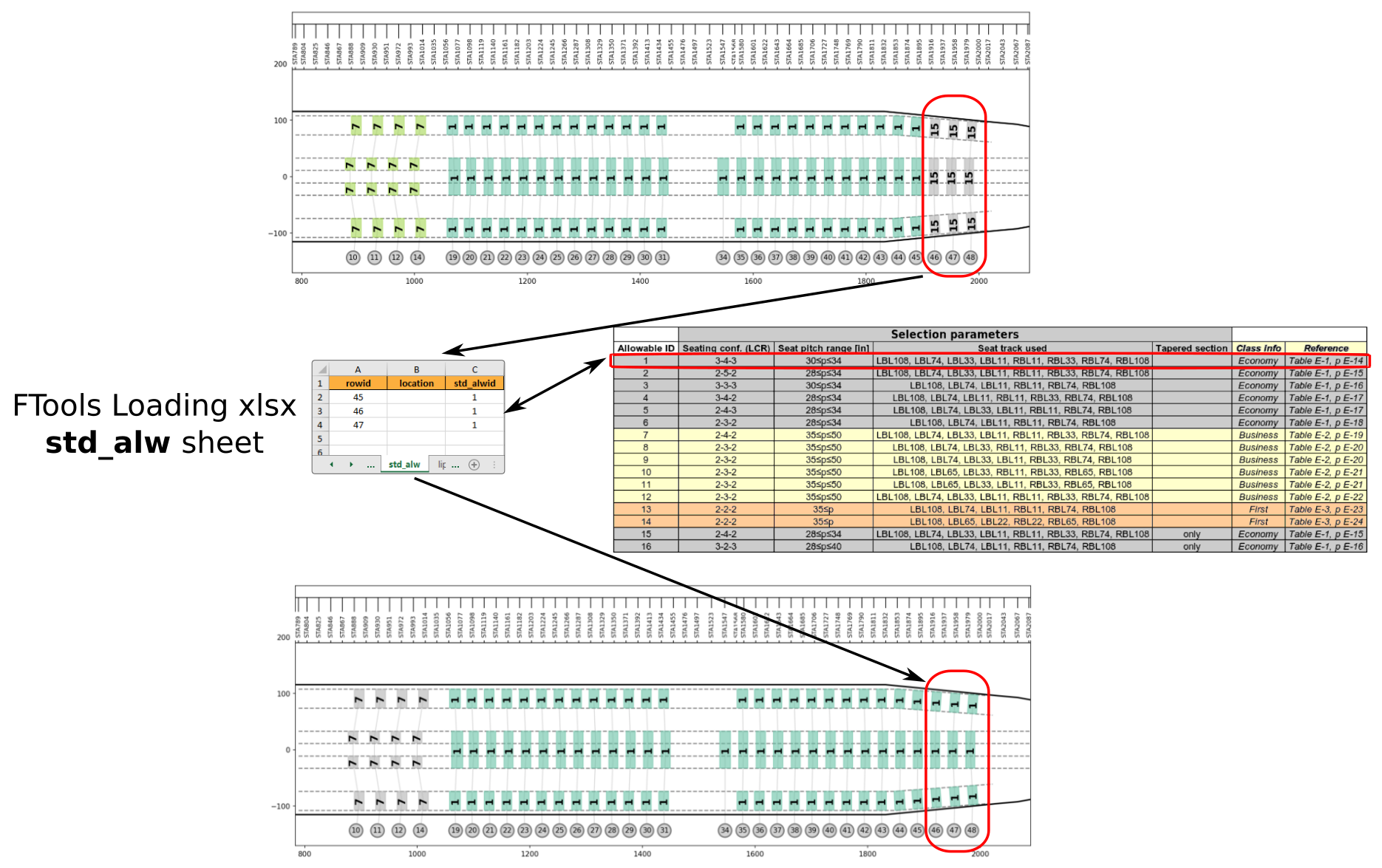
This sheet can be used to override default seat load allowable

By default, FTools automatically associate the most relevant seat load allowable to each seat based on seating configuration, seat pitch, tapered section and seat track used by the seat installation. Thanks to this sheet, FTools user have the possibility to override this load allowable association by a new one.

Fig. 60 illustrates the modification of default standard seat allowable thanks to Sheet “std_alw”.

std seat allowable example

Fig. 60 Example of standard seat load allowable modification

STD_ALW-rowid

type: integer | minimum: 0

Specify the row ID of the seat(s) impacted by the modification of load allowable

STD_ALW-location

default: l,c,r | pattern: ^(?:([lrc])(?!.*?\1),\s*)*[lrc]\s*$ | type: string, null

Specify the transverse location of the seat(s) impacted by the load allowable modification

By default, all seats in the row specified are impacted by the modification. This is equivalent to write ‘l,c,r’ in this field. ‘l’ stands for ‘left’, ‘c’ for center and ‘r’ for right. If only the outboard left seat is impacted by the load allowable modification, ‘l’ should be entered in this field.

STD_ALW-std_alwid

type: integer | minimum: 1 | maximum: 16

Define the ID of seat allowable replacing the default allowable provided by FTools.

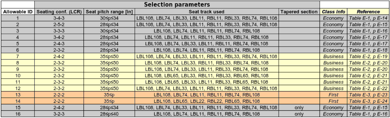
For Boeing B777 aircraft the list of IDs are presented in the following table.

B777 seat load allowable ID

Fig. 61 Boeing B777 standard seat load allowable ID

Table 16 std_alw columns specifications

column

type

min

status

default

max

set

rowid

int

0.0

mandatory

Set (target)

location

string, null

l,c,r

Set (target)

std_alwid

int

1.0

mandatory

16.0

Note

The following set(s) of columns combination need to be unique:

  • Set (target): rowid, location


Sheet “meta

This sheet is used to enter the internal settings and parameters of the FloorTools.

META-key

type: string

Enter parameter key for the internal setting specification

The following ‘keys’ are available:

  • ‘magnet_distance’: parameter used to locate a rail in the vicinity of the specified interface point

  • ‘smallest_element_length’:

  • ‘crossbeams_default_z_offset’: parameter used for the z positioning of the cross beam bar element in the FE model

  • ‘rails_default_z_offset’: parameter used for the z positioning of the seat track bar element in the FE model

  • ‘ac_model’: parameter used to define the aircraft model

META-magnitude

type: string, number

Enter a value corresponding to the parameter ‘key’

META-units

default: "" | type: string, null

Enter a the unit of the value corresponding to the parameter ‘key’

Table 17 meta columns specifications

column

type

status

default

key

str

mandatory

magnitude

string, number

mandatory

units

string, null

“”